Method and apparatus for controlling motor for vehicles

a technology for controlling motors and vehicles, applied in the direction of motor/generator/converter stoppers, dynamo-electric converter control, instruments, etc., can solve the problems of inability to achieve an appropriate torque control, large impedance of motors, and small torque, so as to improve control responsiveness, reduce the accuracy of torque control, and enhance the effect of control responsiveness

Inactive Publication Date: 2008-03-06
DENSO CORP
View PDF7 Cites 30 Cited by
  • Summary
  • Abstract
  • Description
  • Claims
  • Application Information

AI Technical Summary

Benefits of technology

[0018]Thus, the motor control apparatus for vehicles having the above configuration can perform current supply control suitable for temperature by setting a target torque based on detected temperature and power source voltage. Accordingly, irrespective of the level of the temperature at which the motor is used, suitable torque can be generated in the motor with a simple configuration.
[0050]Specifically, a motor to be controlled and an apparatus for controlling the motor can be integrated (modularized). Such an integrated motor control apparatus for vehicles can reliably have various types of information according the electrical and mechanical characteristics of the integrated motor, so that the individual difference of the motor can be reliably absorbed, while more reliably performing appropriate control. The various types of information here include, for example, a target torque, reference impedance compensation amount, target torque map, torque compensation amount and actual current supply pattern. In case a motor and a control apparatus for controlling the motor are established being physically apart from each other, and both of them are connected via a harness or the like, the accuracy of the torque control may be lowered being influenced by the voltage drop caused by the harness. However, the integration of the motor and the control apparatus no longer entails consideration for such an influence of the voltage drop, so that high accuracy control can be effected for a target torque. In addition, the integration can enhance control responsiveness.

Problems solved by technology

Accordingly, this method may not achieve an appropriate torque control depending on the conditions of the vehicle on which the SR motor is loaded or degrees of variations in the components of the SR motor.
Specifically, higher temperatures may result in larger impedance of a motor, hardly allowing a current to flow, and may also result in smaller torque.
However, designing the control apparatuses anticipating the worst particular conditions may contrarily bring about unnecessarily large torque when the apparatuses are in good condition, for example, when they are in low temperatures or close to the upper limit in the tolerance range of dimensional variations caused by assembling.
As a result, the members to be driven (objects to be controlled) by the motor may have a breakdown.
The current F / B control, however, entails providing a current detection resistor and a current detection circuit for each of the current supply paths of the respective phase coils 81, 82 and 83 in the motor, raising a problem that the circuit is unavoidably enlarged.
Accordingly, use of a single current detection resistor and a single current detection circuit may bring about a difficulty in individually detecting the power supply currents that flow through the respective phases, and thus cannot be applied to actual products.

Method used


Image

  • Method and apparatus for controlling motor for vehicles
  • Method and apparatus for controlling motor for vehicles
  • Method and apparatus for controlling motor for vehicles

Examples


Embodiment Construction

[0069]With reference to the accompanying drawings, hereinafter is described an embodiment in which the present invention is applied to a shift range switching mechanism.

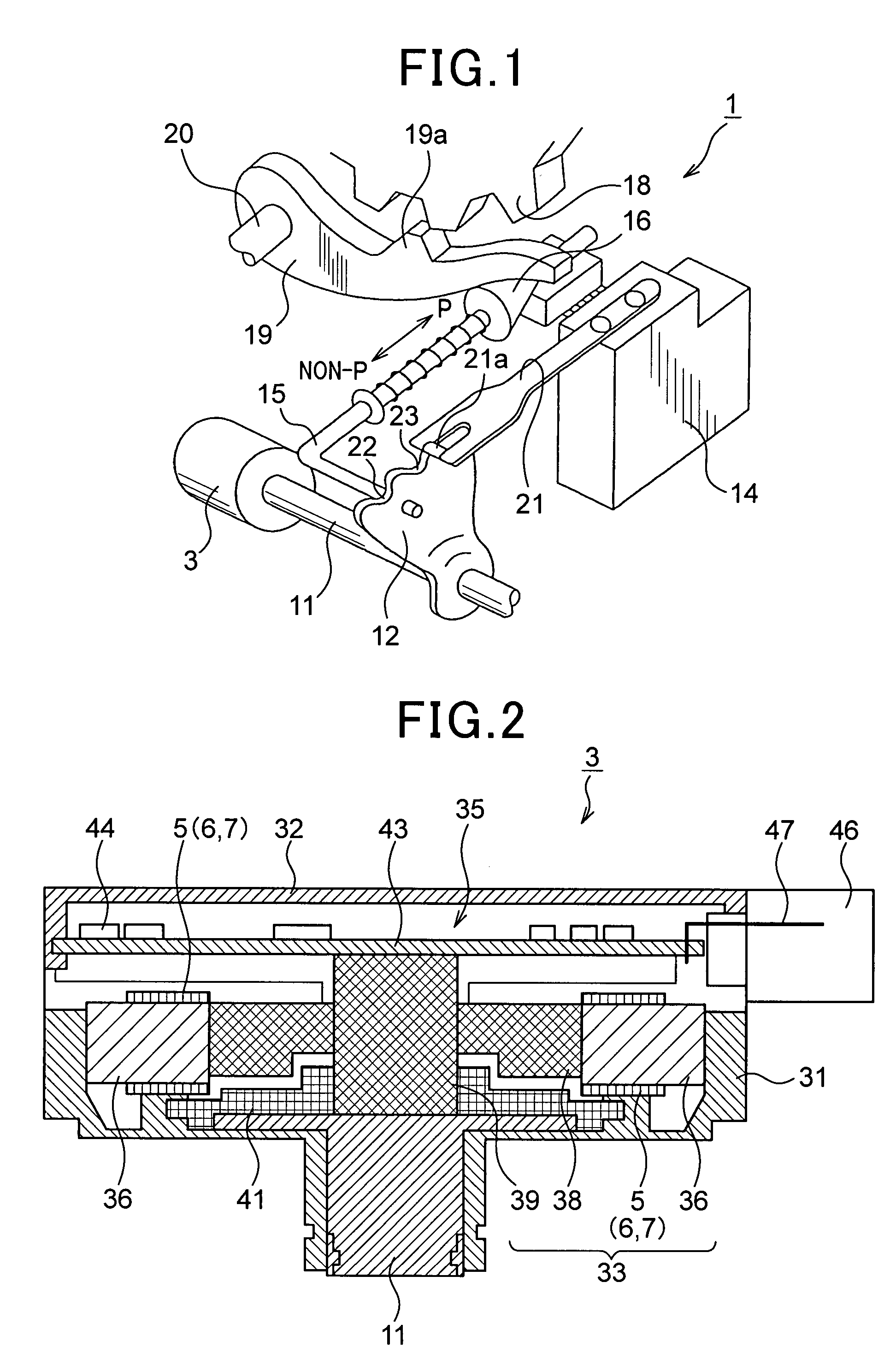
[0070]Referring to FIG. 1, an explanation is given first on a configuration of a shift range switching mechanism 1 according the present embodiment. The purpose of the shift range switching mechanism 1 is to switch a shift range in response to a driver's operation of a shift lever, and is provided with a switching / driving apparatus 3 as a drive source. To simplify the explanation, the following description will be focused on a switching operation from a parking range (hereinafter referred to as a “P range”) to other ranges (hereinafter referred to as a “non-P range”), or vice versa, in the entire shift range switching operation.

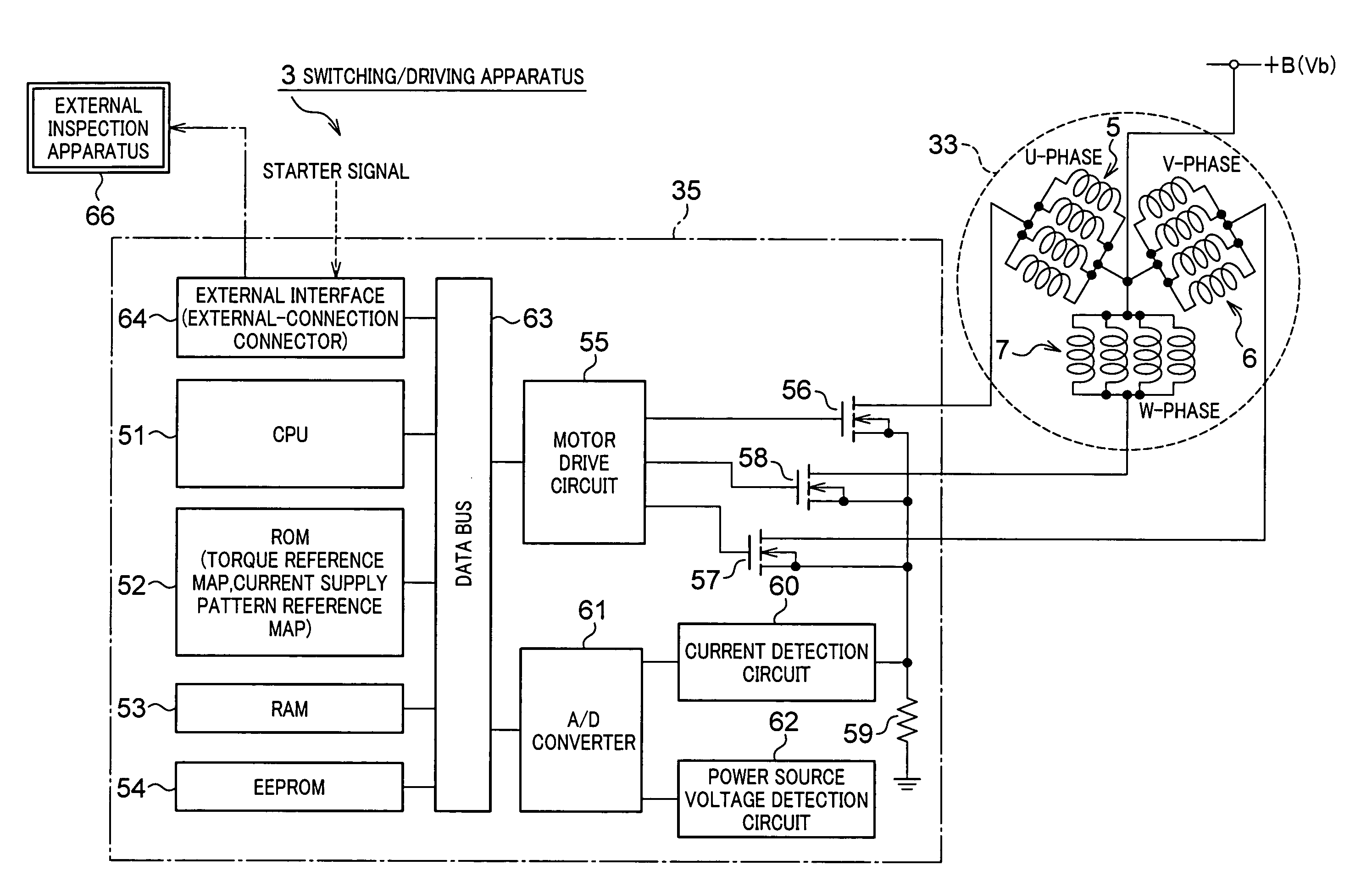
[0071]A detailed configuration of the switching / driving apparatus 3 (see FIG. 2, for example) will be described later, but to put it briefly, the switching / driving apparatus 3 includes a switc...


PUM


Abstract

An apparatus is provided for controlling drive of a motor mounted on a vehicle and formed to have a rotor and a stator equipped with a plurality of phases of coils to be supplied by current in turn, phase by phase, to rotate the rotor. The apparatus comprises a voltage detector, temperature detector, setting block, and current-supply block. Of these, the voltage detector detects a voltage of power to be applied to the motor, while the temperature detector detects a temperature of the motor. The setting block uses the detected temperature and the detected voltage of the power to set a target torque at which the motor should generate a torque. The current-supply block supplies current to the motor so that the motor generates the torque on the target torque set by the setting block.

Description

CROSS-REFERENCE TO RELATED APPLICATION[0001]This application is based on and claims the benefit of priority from earlier Japanese Patent Application No. 2006-237887 filed Sep. 1, 2006, the description of which is incorporated herein by reference.BACKGROUND OF THE INVENTION[0002]1. Field of the Invention[0003]The present invention relates to a motor control apparatus for vehicles for controlling driving of an on-vehicle motor, which includes a rotor and a stator having a plurality of coils, and is configured to rotate the rotor by supplying current to the coils with sequentially switching phases to which the current is supplied.[0004]2. Related Art[0005]Various types of motors have been utilized as driving sources for driving various actuators in vehicles. In particular, reluctance motors typically represented by switched reluctance motors (hereinafter each referred to as an “SR motor”) have such merits as requiring no permanent magnet, having a simple structure, enabling use under h...

Claims


Application Information

Patent Timeline
Patent Type & Authority Applications(United States)
IPC IPC(8): H02P7/00G05D23/00H02P25/08
CPCH02P25/08
Inventor TAMARU, TAKUYA
Owner DENSO CORP
Why Eureka
Try Eureka