
Software based thermal charging regulation loop

a technology of thermal charging and software, applied in the direction of battery overheat protection, safety/protection circuits, transportation and packaging, etc., can solve the problems of damage to onboard silicon components, significant increase in chip temperature,

Active Publication Date: 2008-03-06
AVAGO TECH INT SALES PTE LTD
View PDF10 Cites 3 Cited by
  • Summary
  • Abstract
  • Description
  • Claims
  • Application Information

AI Technical Summary

Benefits of technology

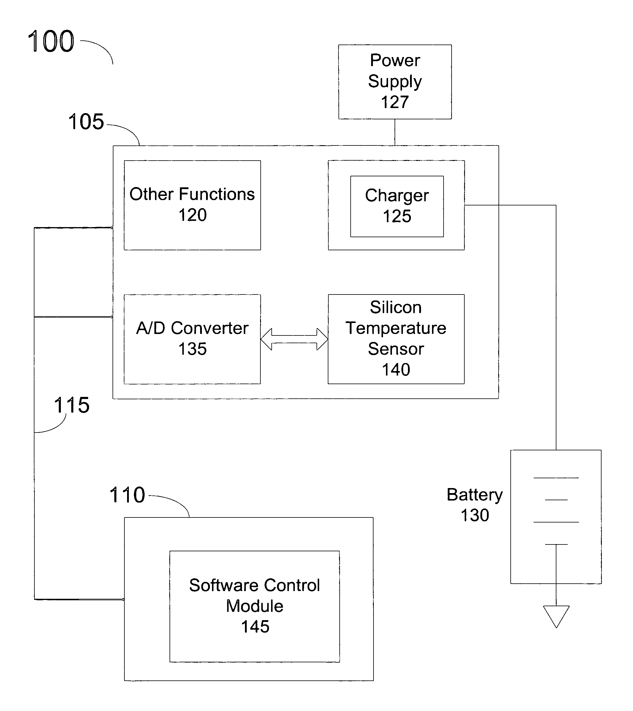
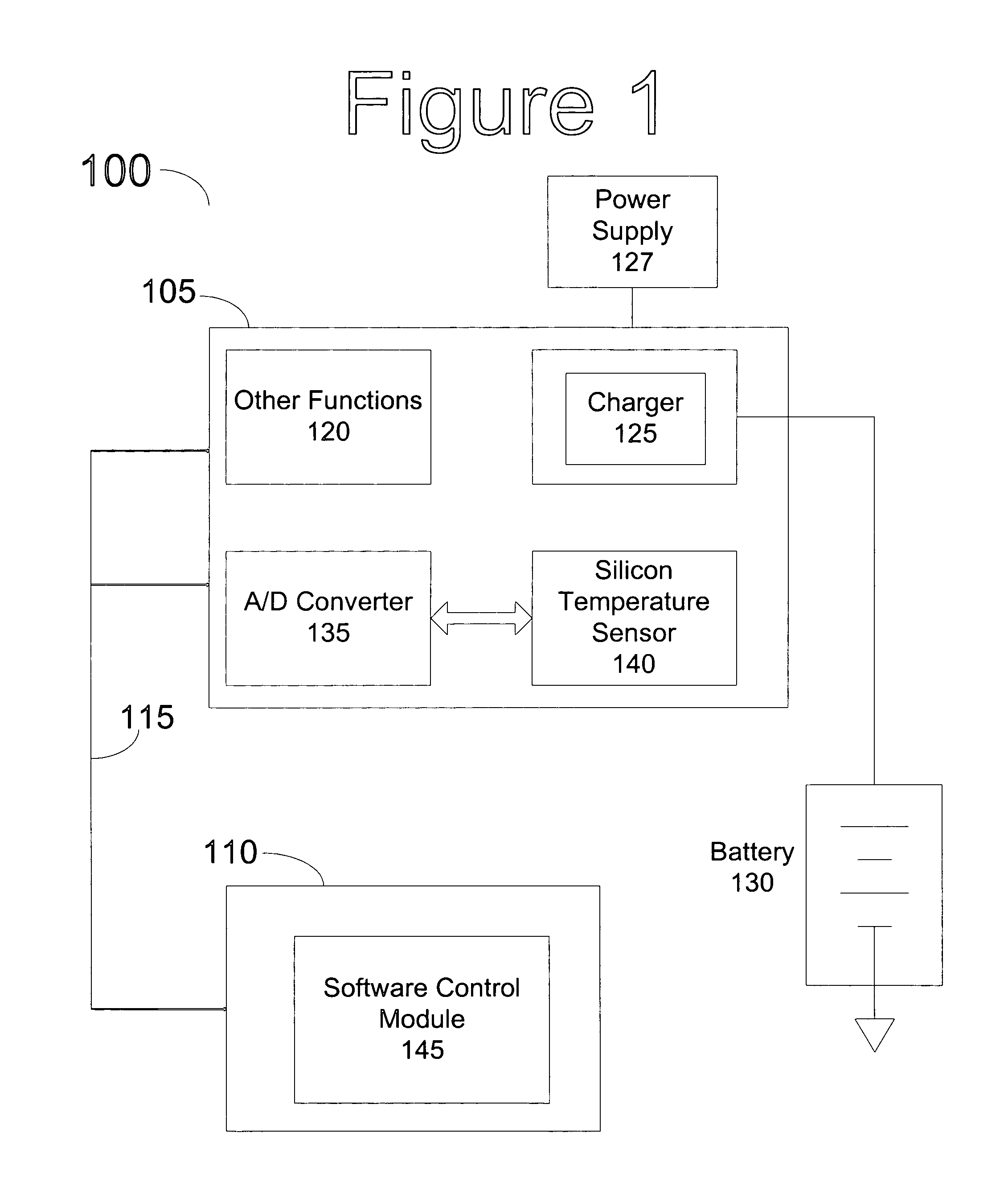
[0008]The present invention implements a software controlled thermal feedback system for battery charging circuitry in portable devices, specifically in cellular telephones. This software controlled charging circuitry allows for a more flexible thermal control system providing upgradeable capabilities built into the software, allowing for thermal control of additional hardware systems.
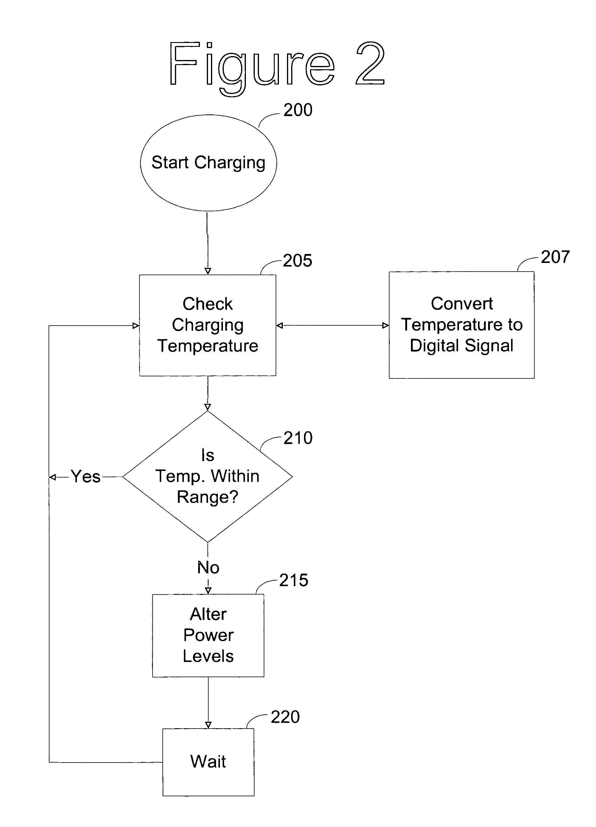
[0011]Thermal control software, implemented on the DBB microcontroller, monitors the silicon temperature of the ABB and adjusts the charging current accordingly to provide a controlled chip temperature during charging. Additionally, since ABB dynamic power is a function of many activities, not relegated to only charging, but to the other functions listed above (e.g., LED control, LCD screen control), the thermal temperature monitoring of the present invention allows for tuning and optimization of the power levels of other functions being controlled by the ABB, providing a higher level of capability to customize the thermal control. By monitoring and adjusting the power levels of other functions controlled by the ABB, the system can keep battery charging power maximized and battery charging time minimized.

Problems solved by technology

However, this charging hardware block can generate significant on-chip thermal heating that could result in a significant increase in the temperature of the chip, possibly damaging onboard silicon components.

Method used


Image

  • Software based thermal charging regulation loop
  • Software based thermal charging regulation loop
  • Software based thermal charging regulation loop

Examples


Embodiment Construction

[0015]Portable devices, such as cellular telephones and personal digital assistants (PDAs) have become more popular in the past few years. Many of these portable devices now come with an integrated rechargeable battery, eliminating the need for buying replacement batteries. However, as portable devices have become more powerful, so too have their batteries. These more powerful batteries require more power to charge, which can cause the charging circuitry to radiate thermal heat throughout the portable device. This heat can cause the internal circuitry of the portable device, for example a cellular telephone, to become damaged or cause performance degradation of any thermally sensitive components in the cellular telephone. The present invention utilizes a software controlled thermal temperature control to maintain a safe temperature during battery charging.

[0016]FIG. 1 illustrates a portable device circuit 100 for use in a cellular telephone. In the circuit, the analog base band circ...


PUM


Abstract

The present invention implements a software controlled thermal feedback system for battery charging circuitry in portable devices, specifically in cellular telephones. The charging hardware block is integrated into a mixed-signal analog base-band (ABB) circuit. In addition to standard function controls, integrated within the ABB are silicon temperature sensors used to monitor the temperature of any silicon components integrated on the ABB and detect any temperature change due to thermal heating. The temperature value is passed to the digital base band (DBB) circuit. Here, a microcontroller is programmed to perform power management functions relating to the ABB. Thermal control software, implemented on the DBB microcontroller, monitors the silicon temperature of the ABB and adjusts the power levels on the ABB accordingly to provide a controlled chip temperature.

Description

FIELD OF THE INVENTION[0001]The present invention pertains to methods for thermal control of charging circuitry during battery charging, and more specifically, towards thermal control of charging circuitry during cellular telephone battery charging.BACKGROUND OF THE INVENTION[0002]Technology related to portable devices, specifically cellular telephones, is changing rapidly. Cellular telephones are becoming smaller, yet more powerful. One related technology that is rapidly changing along with the cellular telephone is battery technology and technology related to battery charging. Cellular telephone batteries are becoming smaller and more powerful, and there are multiple battery types that take advantage of different chemical formulations. One problem, however, related to these new generations of batteries is controlling the heat generated during charging, i.e., thermal control. During charging, a charger with a built-in pass transistor can become dangerously hot and the pass transist...

Claims


Application Information

Patent Timeline
IPC IPC(8): H02J7/04
CPCH02J7/0088H02J7/0029H02J7/007188H02J7/00309
Inventor LOPATA, DOUGLAS D.
Owner AVAGO TECH INT SALES PTE LTD
Learn More