Projector

Inactive Publication Date: 2008-03-06
SEIKO EPSON CORP
View PDF5 Cites 37 Cited by
  • Summary
  • Abstract
  • Description
  • Claims
  • Application Information

AI Technical Summary

Benefits of technology

[0038]According to the above aspect of the invention, since the heat exchanger include the cooling fan and the cooling fan cools the plurality of fins

Problems solved by technology

When dust, lampblack and the like are adhered on a surface of the optical modulator of the projector, image quality of the projected image is deteriorated.
Further, since the optical modulator such as a liquid crystal panel in general is weak against heat, the optical modulator is likely to be degraded by heat-generation on account of the light beam irradiated from the light source device.
According to the mechanism, however, it is difficult to secure sufficient heat-rad

Method used


Image

  • Projector
  • Projector
  • Projector

Examples


first exemplary embodiment

[0062]A first exemplary embodiment of the invention will be described below with reference to the attached drawings.

[0063]Exterior Arrangement

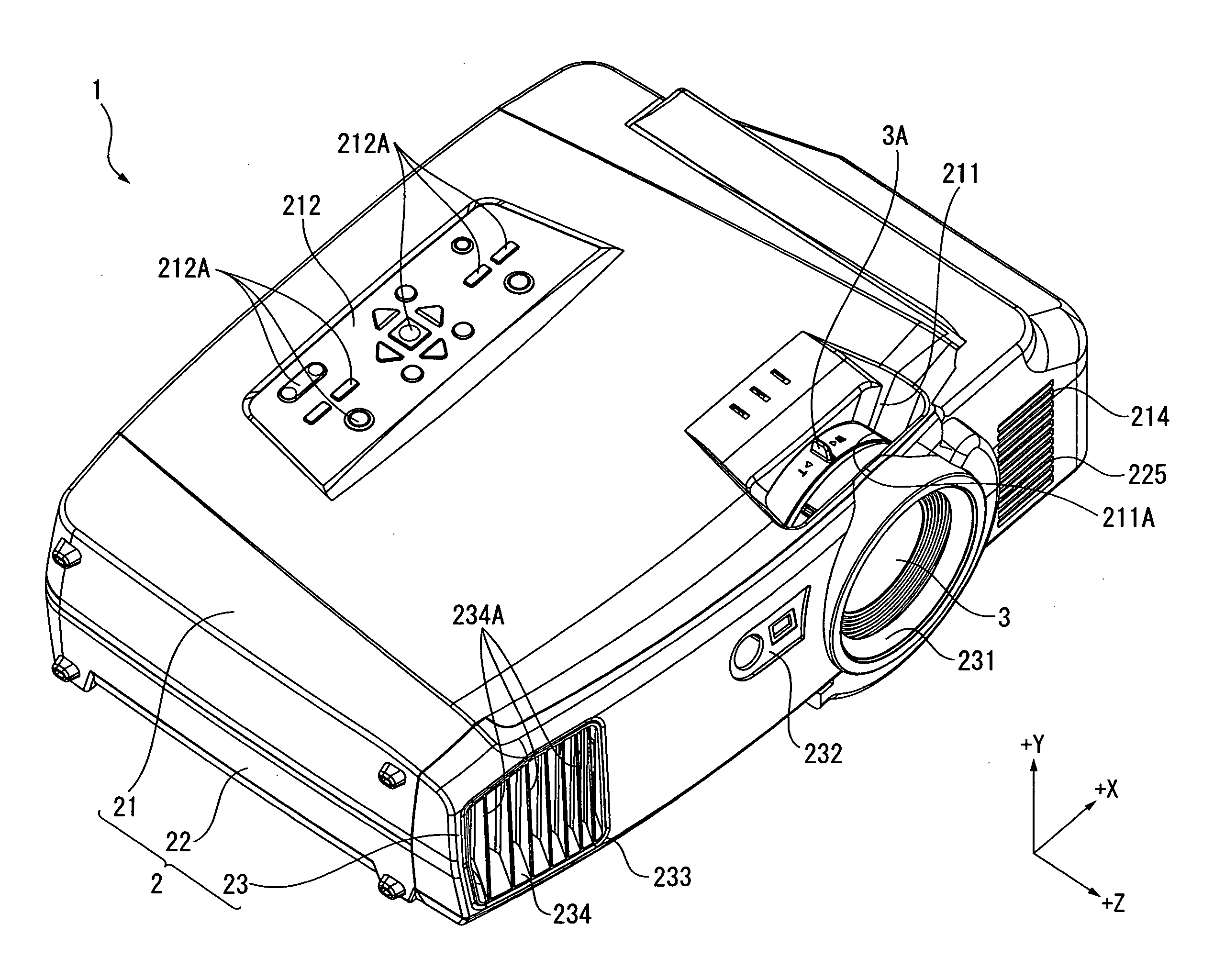
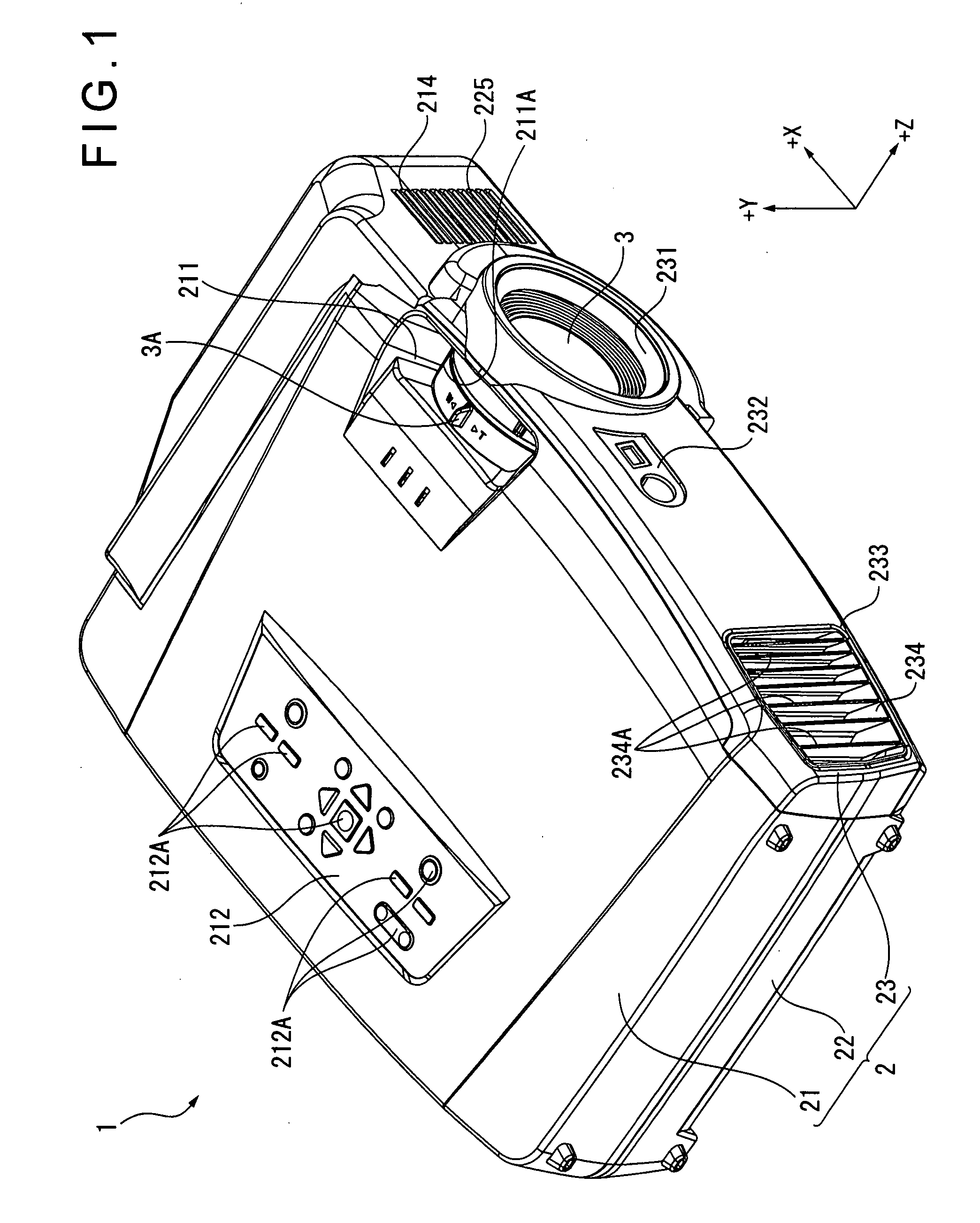
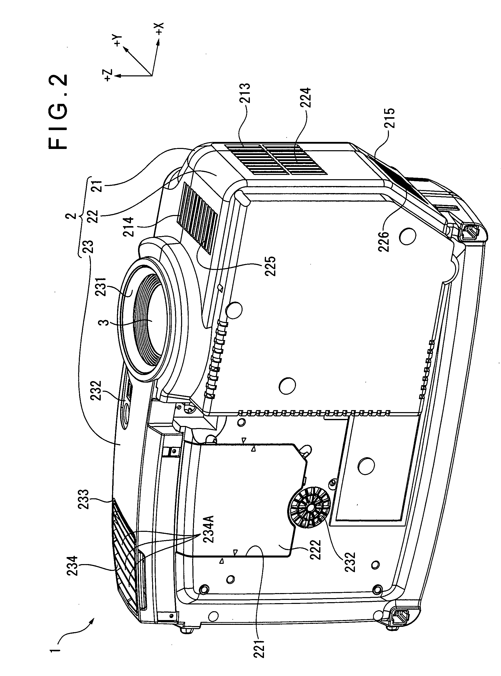
[0064]FIGS. 1 and 2 are perspective views showing an exterior of a projector 1 according to the first exemplary embodiment. Specifically, FIG. 1 is a perspective view showing the upper front side of the projector 1. FIG. 2 is a perspective view showing the lower front side of the projector 1. In FIG. 1, for the convenience of explanation, a projecting direction of an optical image is set as Z-axis and two axes orthogonal to −Z-axis are respectively set as X-axis (horizontal axis) and Y-axis (vertical axis), which applies in the rest of the drawings.

[0065]The projector 1 modulates a light beam irradiated by a light source in accordance with image information to form an optical image and projects the formed optical image on a screen (not shown) in an enlarged manner. As shown in FIGS. 1 and 2, the projector 1 includes a substantially rectangular...

second exemplary embodiment

[0260]A second exemplary embodiment of the invention will be described below with reference to the attached drawings.

[0261]In the following description, the same reference numeral will be attached to the same structures and components as the above-described first exemplary embodiment and detailed description thereof will be omitted or simplified.

[0262]FIG. 22 is an illustration showing an arrangement of the first heat radiator 85A and the second heat radiator 94A of the second exemplary embodiment. Specifically, FIG. 22 is a perspective view showing the lower side of the first heat radiator 85A and the second heat radiator 94A.

[0263]As shown in FIG. 22, the present embodiment differs from the first exemplary embodiment in that the first heat-radiating member 853 and the cooling fan 854 are omitted. The rest of the arrangement is the same as the first exemplary embodiment.

[0264]In the present embodiment, the second ends (condensing portion) of the heat-conducting members 852 and 942 ...


PUM


Abstract

A projector includes: an optical component; a sealed structure within which the optical component casing is disposed, the sealed structure including: a loop air-circulation path in which air is circulated; an optical component casing having an inlet for the air to flow into the optical component casing and an outlet for the air to flow out of the optical component casing; a plurality of ducts that introduces the air into the optical component casing through the inlet and re-introduces the air flowing out of the optical component casing through the outlet into the optical component casing through the inlet; and a heat radiator having a heat-receiving member disposed inside the sealed structure to receive the heat of the air within the sealed structure and a heat-conducting member that penetrates an inside and an outside of the sealed structure, the heat-conducting member having a first end disposed inside the sealed structure and coupled to the heat-receiving member in a heat-transferable manner to transfer the heat of the heat-receiving member to a second end of the heat-conducting member disposed outside the sealed structure; and a circulation fan that circulates the air within the loop air-circulation path.

Description

[0001]The entire disclosure of Japanese Patent Application No. 2006-235658, filed on Aug. 31, 2006, is expressly incorporated by reference herein.BACKGROUND[0002]1. Technical Field[0003]The present invention relates to a projector.[0004]2. Related Art[0005]A projector that has a light source device, an optical modulator for modulating the light beam irradiated by the light source device in accordance with image information and a projection optical device for projecting the light beam modulated by the optical modulator is known.[0006]When dust, lampblack and the like are adhered on a surface of the optical modulator of the projector, image quality of the projected image is deteriorated. Further, since the optical modulator such as a liquid crystal panel in general is weak against heat, the optical modulator is likely to be degraded by heat-generation on account of the light beam irradiated from the light source device.[0007]In order to ensure stable image quality of the projected ima...

Claims


Application Information

Patent Timeline
IPC IPC(8): G03B21/16
CPCG03B21/16
Inventor MOMOSE, YASUNAGAYANAGISAWA, YOSHIYUKI
Owner SEIKO EPSON CORP
Why Eureka
Try Eureka