Surface Strain Measuring Device

a measuring device and surface strain technology, applied in the field of surface strain measuring devices, can solve the problems of difficult precise measurement of surface strains, symptomatic internal stress may give rise to defects, and static devices for measuring purposes do not usually enable temperature variation rates of more than 1° c./s

Active Publication Date: 2008-03-06
INSIDIX
View PDF9 Cites 22 Cited by
  • Summary
  • Abstract
  • Description
  • Claims
  • Application Information

AI Technical Summary

Benefits of technology

[0016] It is an object of the invention to remedy these shortcomings and, in particular, to propose a combination of optical measuring means for measuring the topography and absolute and relative strains in the plane and along an axis perpendicular to this plane (for the different assembled parts). These optical measuring means are associated with a thermal stressing means that enables stressing to be performed representative of the thermal gradients encountered during fabrication, assembly or operation of the components and printed circuit...

Problems solved by technology

These strains symptomatic of internal stresses may give rise to defects, for example interface defects, surface warpage or opening of electric circuits at the level of the inter-connections between different components of a microelectronic and/or electronic assembly.
Component fabrication processes, like the principle of movement of the sample on assembly, do however make precise measurement of these strains difficult.
Moreover, static devices for measuring purposes do not usually enable temperature variation rates of more than 1° C./s to be achieved.
However, these techniques create an uncertainty when the strain creates an offset greater than the characteristic length of the structured illumination...

Method used


Image

  • Surface Strain Measuring Device
  • Surface Strain Measuring Device
  • Surface Strain Measuring Device

Examples


Embodiment Construction

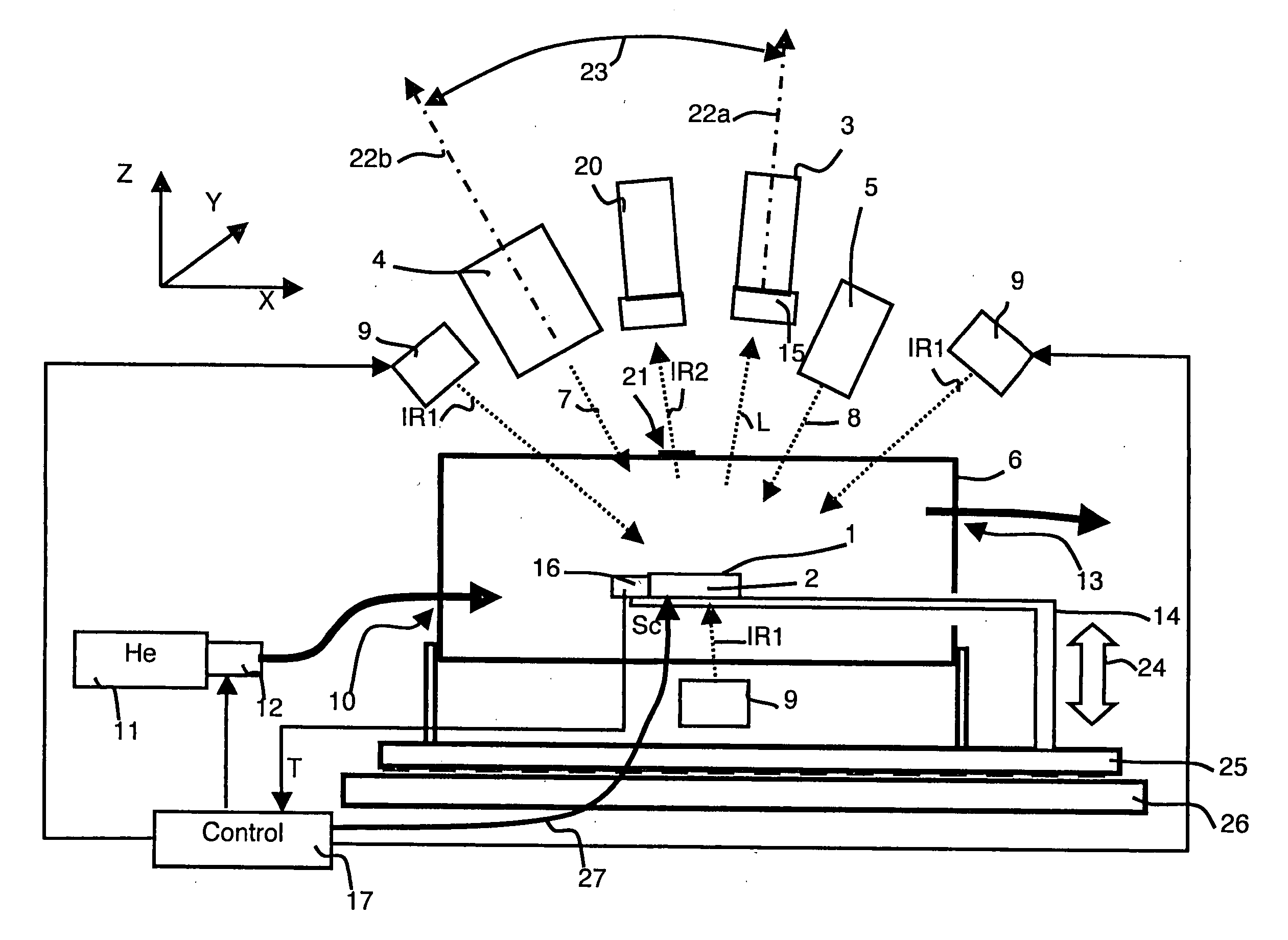
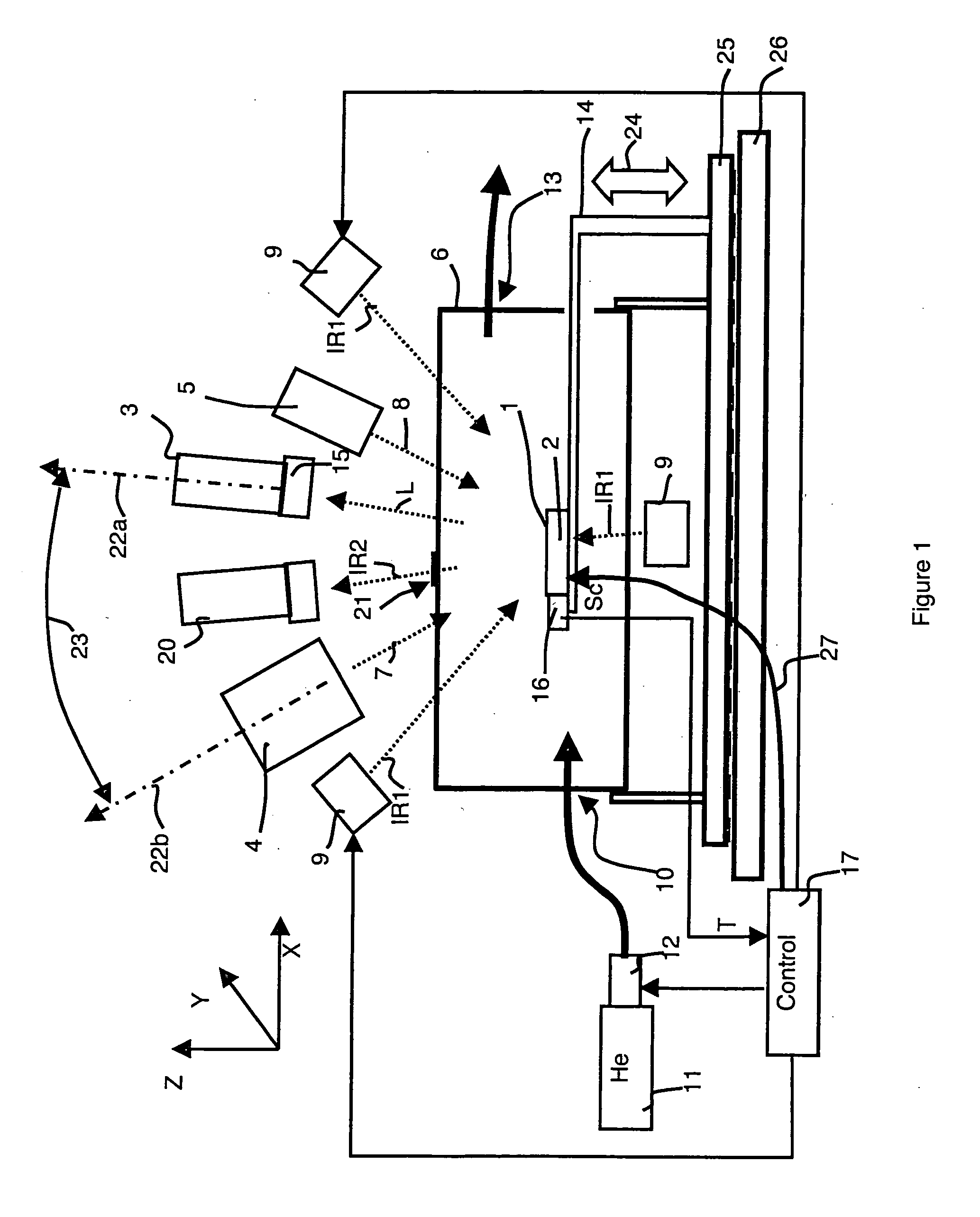
[0029]FIG. 1 represents a device for measuring strains of a surface 1, for example a flat surface, of a sample 2 according to the temperature. The device comprises a visible light detection camera 3 and a first light source 4 for structured illumination of the sample 2 with a structured light to measure movements or strains that are perpendicular to the plane of the surface 1 of the sample 2.

[0030] The technique used for structured illumination comprises projection of composite images. This technique is carried out by illumination of the surface 1 with a sequence of images. As represented in FIG. 5, each image comprises a periodic pattern M (M1, M2, M3) and the periodic patterns of the different images of the sequence of images respectively present pitches of different periodicities. Such a technique in particular enables the topography to be defined in absolute manner, unlike Moiré type techniques that are sensitive only to differences of topography and, in addition, only to diffe...


PUM


Abstract

The device enables strains of at least one surface (1) of a sample (2) to be measured versus temperature. Strains in a direction perpendicular to a predetermined plane, for example the plane of the surface (1), are measured by composite images. Strains in said plane are measured by image correlation. The measurements by image correlation and by composite images use a common visible light detection camera (3). The sample (2) is arranged in an enclosure (6) transparent at least locally to visible light (L). At least one infrared emitter (9) enables an infrared light to be created in a spectral band for a large part not detected by the camera (3).

Description

BACKGROUND OF THE INVENTION [0001] The invention relates to a device for measuring topographies and strains of at least one surface of a sample, comprising [0002] first measuring means for measuring topographies and movements that are perpendicular to a predetermined plane, [0003] second measuring means for measuring strains that are in a plane defined by the surface, by image correlation, the first and second measuring means using at least one common light detection camera, [0004] heating means and means for measuring the temperature of the sample. STATE OF THE ART [0005] Materials and assemblies, for example electronic and microelectronic materials and assemblies, usually undergo strains due to the effect of thermomechanical effects during fabrication, during assembly on a printed circuit board and in the course of operation. These strains symptomatic of internal stresses may give rise to defects, for example interface defects, surface warpage or opening of electric circuits at th...

Claims


Application Information

Patent Timeline
IPC IPC(8): G01L1/24G01B11/16G01B11/25
CPCG01B11/162
Inventor LECOMTE, JEAN-CLAUDEFAYOLLE, ROMAIN
Owner INSIDIX
Why Eureka
Try Eureka