Tone Setting for Monochrome Image

a color tone and monochrome technology, applied in the field of color tone of monochrome images, can solve the problems of increasing the time required for such processing, and it is not easy to set and achieve the effect of easy setting of the color tone of a monochrome imag

Inactive Publication Date: 2008-03-06
SEIKO EPSON CORP
View PDF7 Cites 20 Cited by
  • Summary
  • Abstract
  • Description
  • Claims
  • Application Information

AI Technical Summary

Benefits of technology

[0018]The present invention was devised in order to address the above issues, and a main object thereof is to provide a technology to enable a color tone of a monochrome image to be easily set.

Problems solved by technology

In the above configuration, it is not easy to set a color tone of a monochrome image to a desired color tone.
Furthermore, the time required for such processing increases dramatically due to the trial and error operations required to set the color tone of the monochrome image.

Method used


Image

  • Tone Setting for Monochrome Image
  • Tone Setting for Monochrome Image
  • Tone Setting for Monochrome Image

Examples


first embodiment

A. FIRST EMBODIMENT

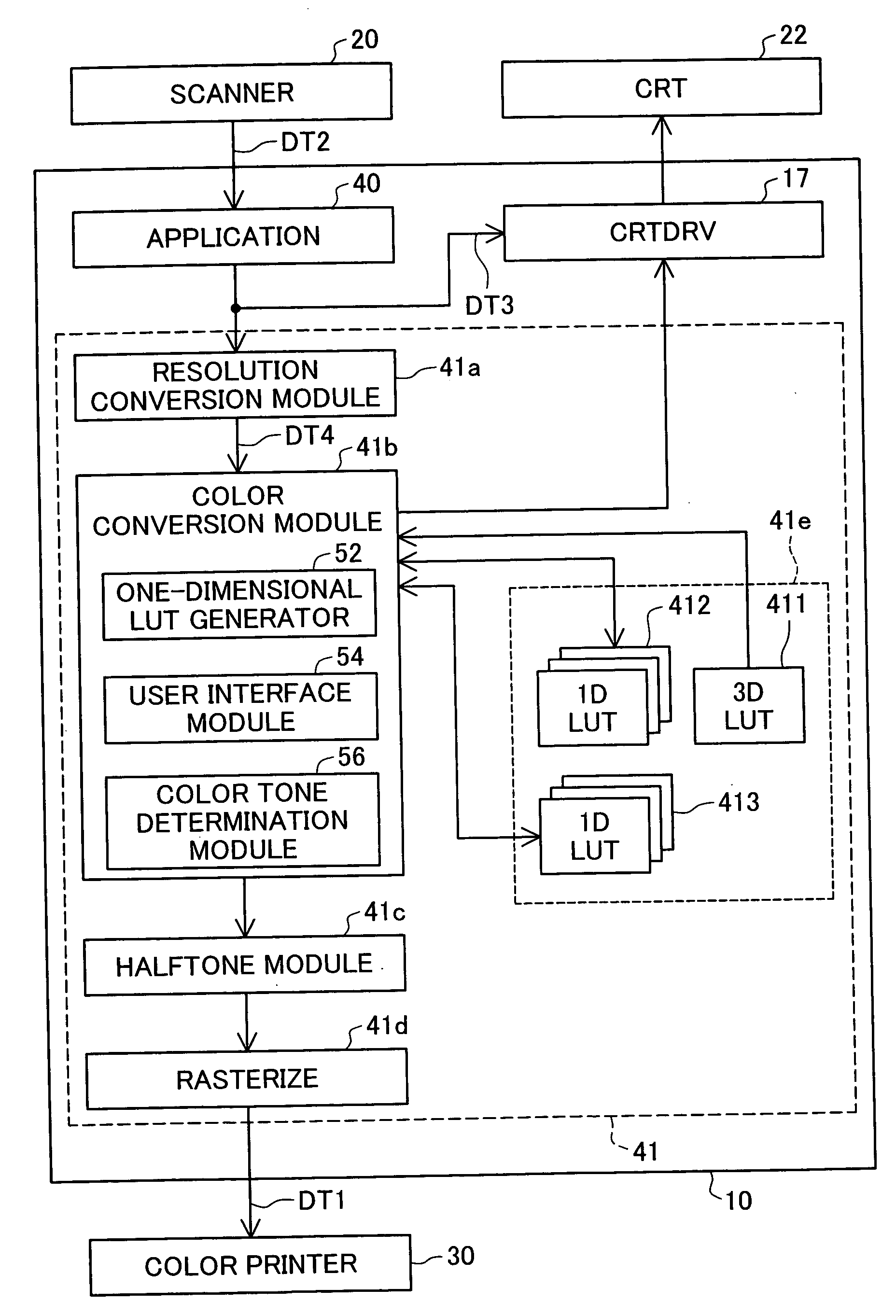
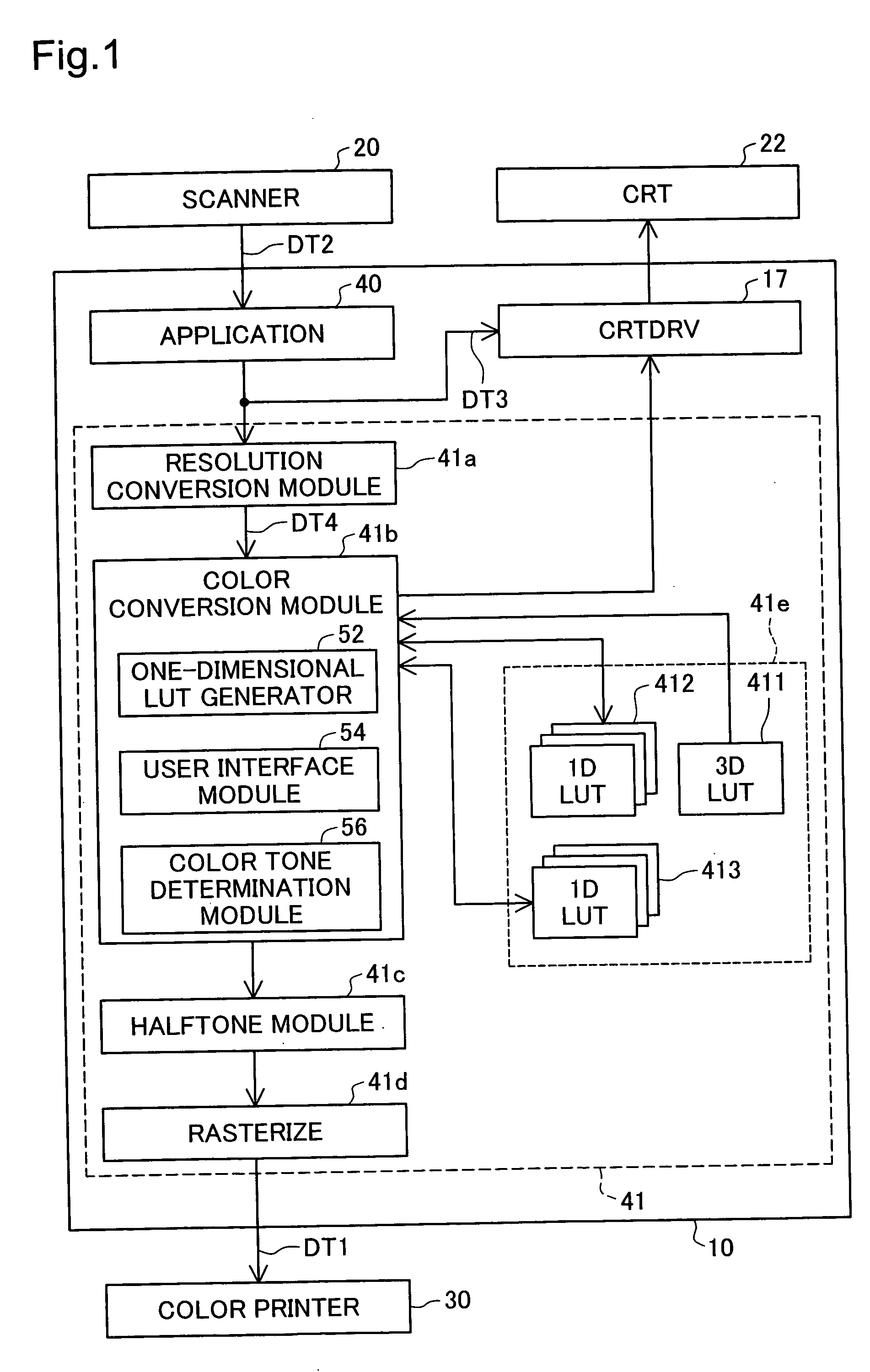
[0081]FIG. 1 is a block diagram showing in a conceptual fashion a technology for printing monochrome images using a color printer pertaining to a first embodiment of the present invention. This technology differs from the configuration shown in FIG. 11 in regard to the construction of the color conversion table 41e and the functions of the color conversion module 41b. The color conversion module 41b has a one-dimensional lookup table generator 52 that generates a one-dimensional lookup table used for printing of a monochrome image, a user interface module 54 that displays a color tone setting window on a display device (CRT 22), and a color tone setting module 56 that determines the tone of the monochrome image based on the settings in the color tone setting window. The functions of the color conversion module 41b are described in detail below.

[0082]The grey image whose color tone is to be assigned by the color conversion module 41b may be a grey image read by a s...

second embodiment

B. SECOND EMBODIMENT

[0105]FIGS. 10A and 10B are explanatory drawings showing the color tone setting windows 100, 200 of a second embodiment. The color tone setting window 100 shown in FIG. 10A is virtually identical to that shown in FIG. 5, and differs only in that it includes tabs 101, 102 at the upper part of the window. When the user selects the first tab 101, the first color tone setting window 100 shown in FIG. 10A is displayed, while when the user selects the second tab 201, the second color tone setting window 200 shown in FIG. 10B is displayed.

[0106]The second color tone setting window 200 includes instead of the ink color circle 110 three ink color sliders 211-213, as well as a sample image display area 120, a tone determination button 140 and four reference tone setting buttons 150, 160, 170 and 180. The ink color sliders 211-213 are used by the user to set the intensity of each of the three ink color components of cyan, magenta and yellow. The value at the center of each ...

third embodiment

C. THIRD EMBODIMENT

[0114]FIG. 11 is an explanatory drawing showing a method for determining the color component intensity values Ic, Im, Iy representing chromatic primary color inks from a specified point Pcc in a third embodiment. This method differs from the method described with reference to FIG. 6 in the following two ways:

[0115](Difference 1) The specified point Pcc in the ink color circle 110 is used as the corresponding point Pt as is.

[0116](Difference 2) The method for calculating the three color component intensity values Ic, Im, Iy differs from the method described with reference to FIG. 6.

[0117]Difference 1 means that mapping from the ink color circle 110 to the ink color triangle 112 as described with reference to FIG. 8 is not performed. Therefore, in this embodiment, regions in the ink color triangle 112 that fall outside the ink color circle 110 (i.e., the regions shaded in the drawing) are not used.

[0118]Difference 2 is as follows: the color component intensity value...


PUM

PropertyMeasurementUnit
color toneaaaaaaaaaa
lengthsaaaaaaaaaa
circumferenceaaaaaaaaaa

Abstract

A color tone setting window 100 that includes an ink color circle 110 is displayed in order to set a color tone of a monochrome image. By specifying a point Pcc in the ink color circle 110, intensities of color components representing three chromatic primary color inks are specified. The color component intensities representing three chromatic primary color inks are determined as parameters defining the color tone of the monochrome image in accordance with the position of the specified point Pcc in the ink color circle 110. The ink color circle 110 is configured such that the color component intensities representing three chromatic primary color inks can be visually recognized from the position in the ink color circle 110. Alternatively, ink color sliders can be used in lieu of the ink color circle 110.

Description

TECHNICAL FIELD[0001]This invention relates to a technology for setting a color tone of a monochrome image.BACKGROUND ART[0002]FIG. 16 is a block diagram showing in a conceptual fashion a technology to print color images using a color printer. A scanner 20 outputs to a computer 10 image data DT2 indicating a read image. The computer 10 displays the image on the CRT 22 based on the image data DT2 and causes the color printer 30 to print the image. Where it is desired to print the read image in color, R, G and B signals (hereinafter collectively termed ‘RGB signals’) indicating the amounts of red, green and blue in the image are used as the image data DT2.[0003]In the computer 10, an application program 40 is run under the control of a prescribed operating system. CRT driver software 17 and printer driver software 41 are incorporated in this operating system. Image data DT1 to be relayed to the color printer 30 is output from the application program 40 via the printer driver software ...

Claims


Application Information

Patent Timeline
Patent Type & Authority Applications(United States)
IPC IPC(8): G03F3/08H04N1/46
CPCH04N1/465
Inventor YOSHIDA, SEISHIN
Owner SEIKO EPSON CORP
Why Eureka
Try Eureka