Flexible Base Material and Flexible Image-Displaying Device Resistant to Plastic Deformation

Active Publication Date: 2008-03-06
UDC IRELAND
View PDF2 Cites 154 Cited by
  • Summary
  • Abstract
  • Description
  • Claims
  • Application Information

AI Technical Summary

Benefits of technology

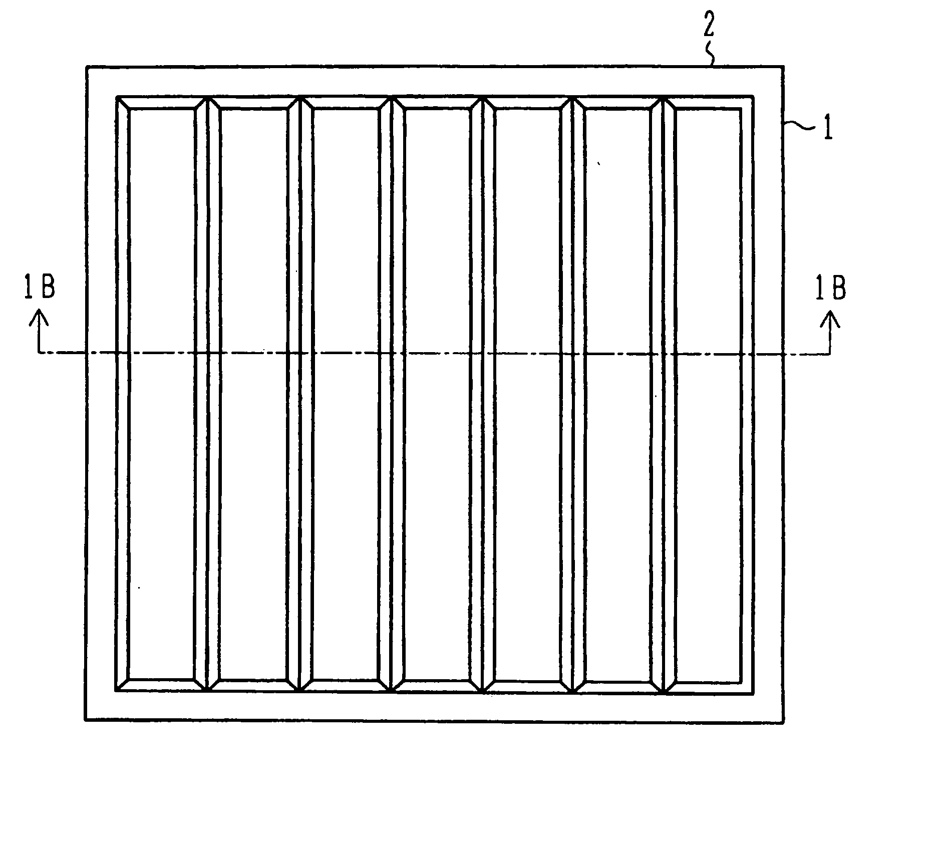
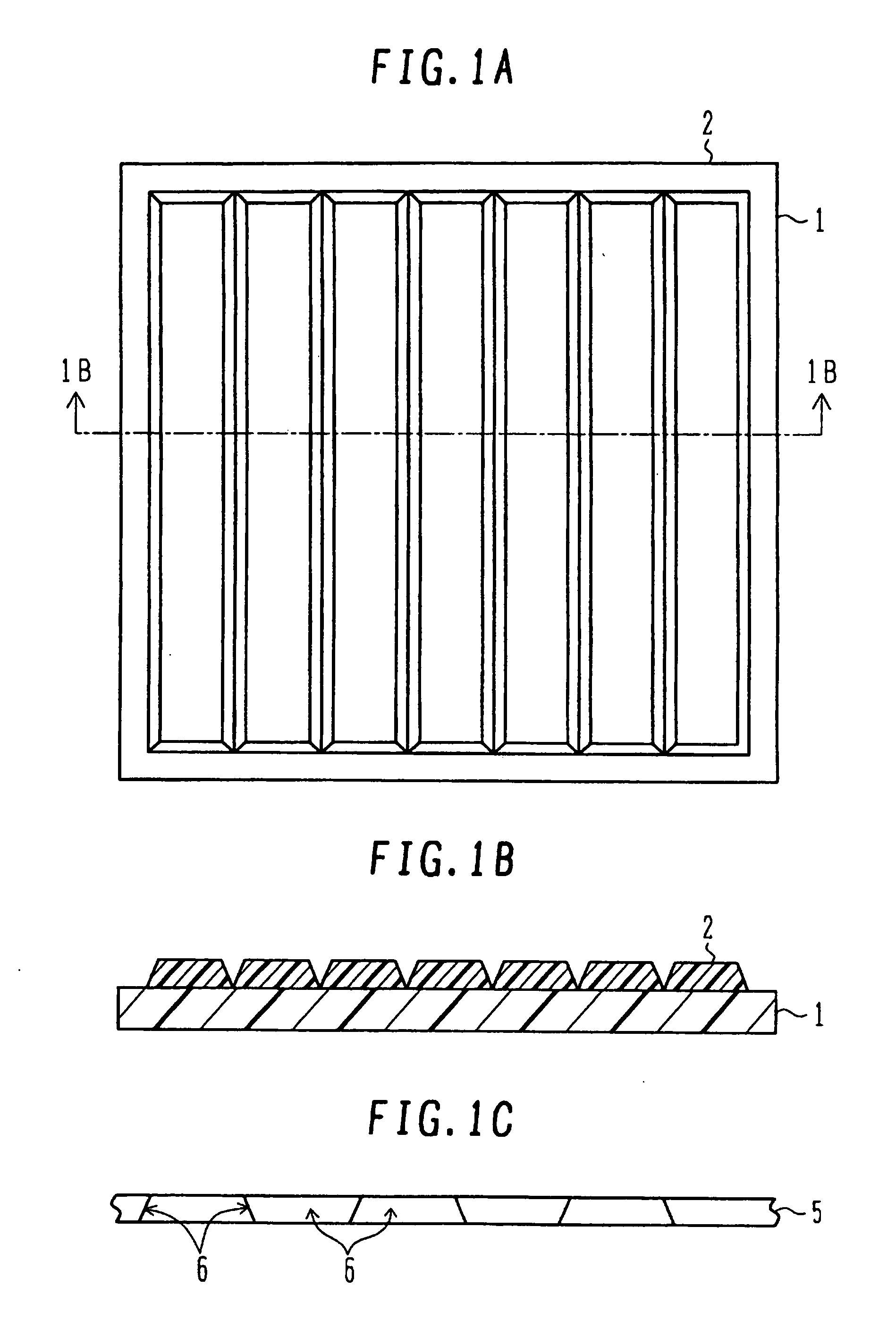
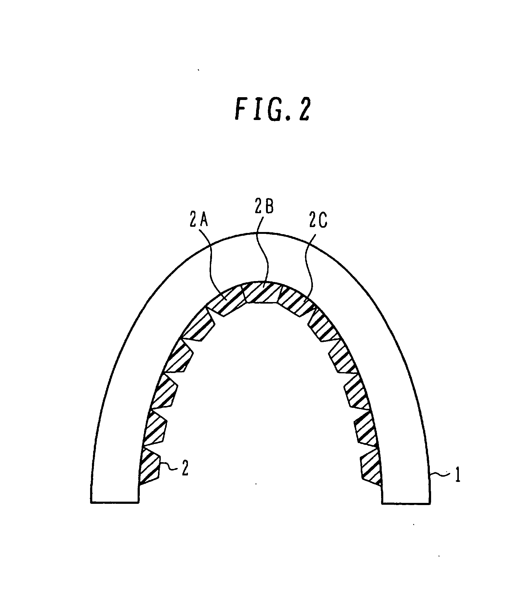
[0011] According to an aspect of the present invention, there is provided a flexible base material, comprising a flexible plate-shaped part and an anti-deformation structure formed on the surface of the plate-shaped part, wherein the anti-deformation structure includes protrusions and depressions on the surface of the plate-shaped part and the protrusions and depressions are shaped such that the adjacent protrusions come into contact with each other when the plate-shaped part is bent within a range of elastic deformation and restrict further deformation.
[0012] Another aspect of the present invention provides a flexible image-displaying device, comprising an image-displaying plate having multiple pixels formed on the surface of a flexible film and a flexible base m

Problems solved by technology

However, bending beyond a range of elastic deformation leads to permanent deformation, which in turn causes whitening of the deformed members.
Thus, bending of a flexible display device

Method used


Image

  • Flexible Base Material and Flexible Image-Displaying Device Resistant to Plastic Deformation
  • Flexible Base Material and Flexible Image-Displaying Device Resistant to Plastic Deformation
  • Flexible Base Material and Flexible Image-Displaying Device Resistant to Plastic Deformation

Examples


ninth embodiment

[0068] The paper-like display is a generic term for thin displays such as paper, and examples thereof so far proposed include horizontally-transporting electrophoretic displays transporting charged particles in the horizontal direction (in-plane direction) such as the flexible image-displaying device in the ninth embodiment, and other various systems. Examples of the other systems include microcapsular electrophoretic displays, twisting-pole displays, electric field precipitation displays, melting displays, and the like. The flexible base materials in the first to eighth exemplary embodiments can be applied to these various paper-like displays.

[0069] Hereinafter, the flexible image-displaying device in the first exemplary embodiment will be described with reference to FIGS. 11A and 11B. In the flexible image-displaying device in the first exemplary embodiment, one of the flexible base materials in the first to eighth exemplary embodiments is applied to the flexible image-displaying ...

eleventh embodiment

[0076] Hereinafter, the flexible image-displaying device in an eleventh exemplary embodiment will be described with reference to FIGS. 12A and 12B. In the flexible image-displaying device in the eleventh embodiment, the flexible base material in the first to eighth exemplary embodiment is applied to a flexible image-displaying plate, for example, to a liquid crystal display element.

[0077]FIG. 12A is a sectional view illustrating the regions at both terminals of the flexible image-displaying device in the eleventh exemplary embodiment, and FIG. 11B is a sectional view of the multiple-pixel region. A pair of flexible substrates 60 and 65 having a thickness of approximately 100 μm is disposed as separated by a certain distance. Transparent electrodes 61 and 66 for example of ITO are formed respectively on the internal surfaces of the substrates 60 and 65. The substrates 60 and 65 are generally, mainly made of PET, PC, PES, or the like, and have a structure laminated with a gas barrier ...


PUM


Abstract

An anti-deformation structure is formed on the surface of a flexible plate-shaped part. The anti-deformation structure includes protrusions and depressions formed on the surface of the plate-shaped part. The protrusions and depressions has a shape in which adjacent protrusions become in contact with each other in the state when the plate-shaped part is deformed within a range of elastic deformation, restricting further greater deformation, and thus, preventing excessive deformation leading to permanent deformation and raising the resistance to the stress. The flexible base material can be applied to flexible image-displaying devices.

Description

TECHNICAL FIELD [0001] The present invention relates to a flexible base material and a flexible image-displaying device, and in particular, to a flexible base material and a flexible image-displaying device resistant to plastic deformation. BACKGROUND ART [0002] As the realization of an ubiquitous society approaches, there are great hopes for the development of wearable display devices. A wearable display device is a flexible device consisting of a flexible substrate and a display element formed thereon. Examples of such display devices include liquid crystal display elements, organic electroluminescent (organic EL) elements, and paper-like displays (electronic paper). [0003] For example, a polymeric material such as polyimide has been used for the flexible substrate. Such substrates can be bent within a range of elastic deformation without generating plastic deformation (permanent deformation) up to a curvature radius of about several mm. However, bending beyond a range of elastic ...

Claims


Application Information

Patent Timeline
IPC IPC(8): G09G3/00B32B33/00
CPCG02F1/133305G09F9/30H01L51/0097H01L51/52Y10T428/24355H05K1/0281H05K2201/09909H05K2201/2009Y02E10/549H01L2251/5338H10K77/111H10K50/80H10K2102/311
Inventor SATOH, TASUKU
Owner UDC IRELAND
Why Eureka
Try Eureka