

Temperature detecting device, fixing device, and image forming apparatus
- Summary
- Abstract
- Description
- Claims
- Application Information
AI Technical Summary
Benefits of technology
Problems solved by technology
Method used
Image

Examples
first embodiment
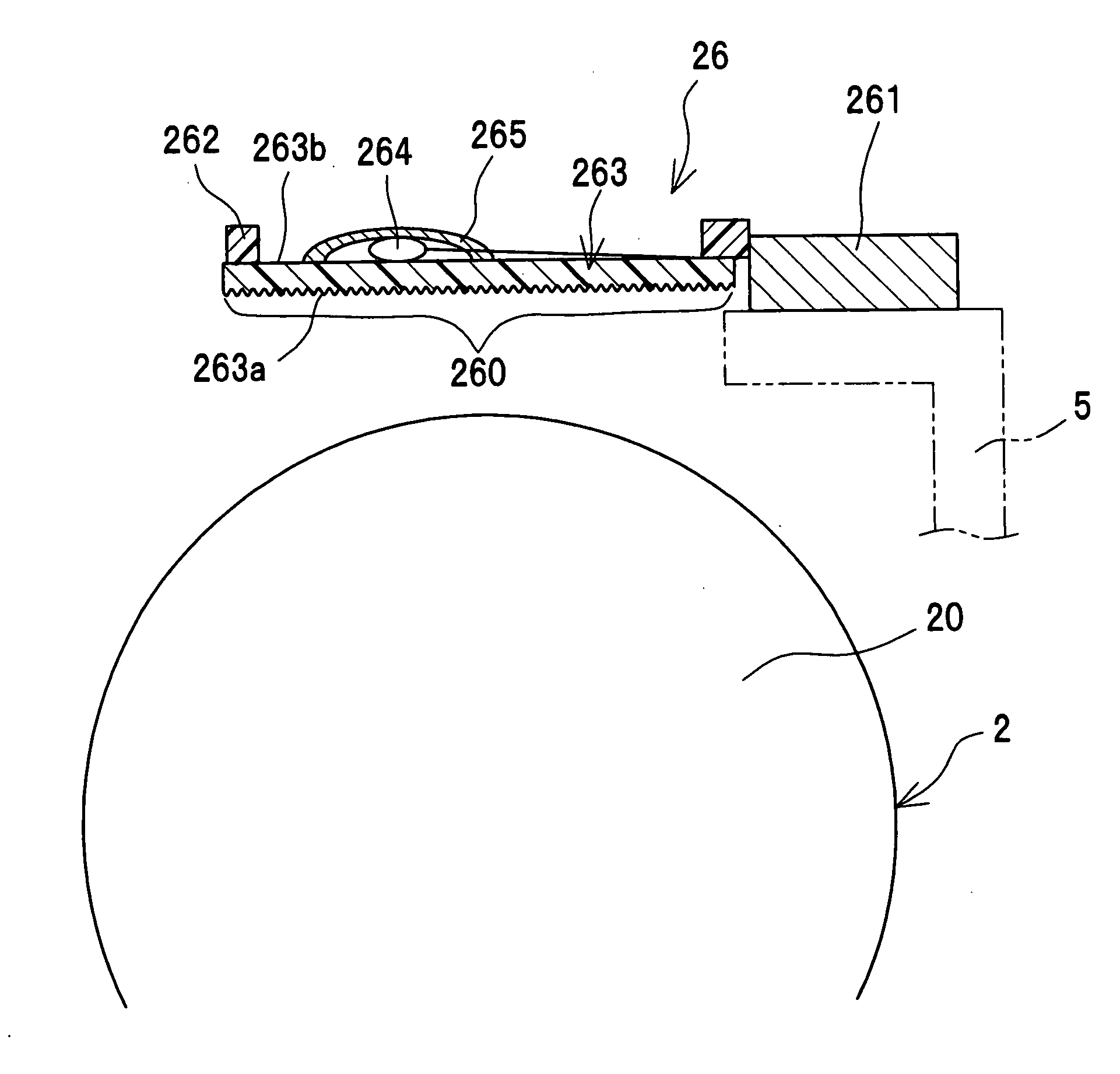
[0024]FIG. 1 shows a schematic structural view of a fixing device according to a first embodiment of the present invention. The fixing device has a heating rotation unit 1 and a pressurizing rotation unit 2. The heating rotation unit 1 is heated by a heater 15 as a heating part. The pressurizing rotation unit 2 is also heated by a heater 25 as a heating part.
[0025]Then, a pair of rotation units 1 and 2 come in contact with each other so as to convey a recording material S and concurrently fix a toner “t” on the recording material S. Specifically, the contact between the heating rotation unit 1 and the pressurizing rotation unit 2 forms a nip portion, which allows the recording material S to be conveyed while the toner t on the recording material S is fused and fixed.
[0026]The recording material S is a sheet such as a sheet of paper, an OHP sheet or the like. The toner t adheres to one surface of the recording material S. The toner t is made of a material having a thermofusibility su...
second embodiment
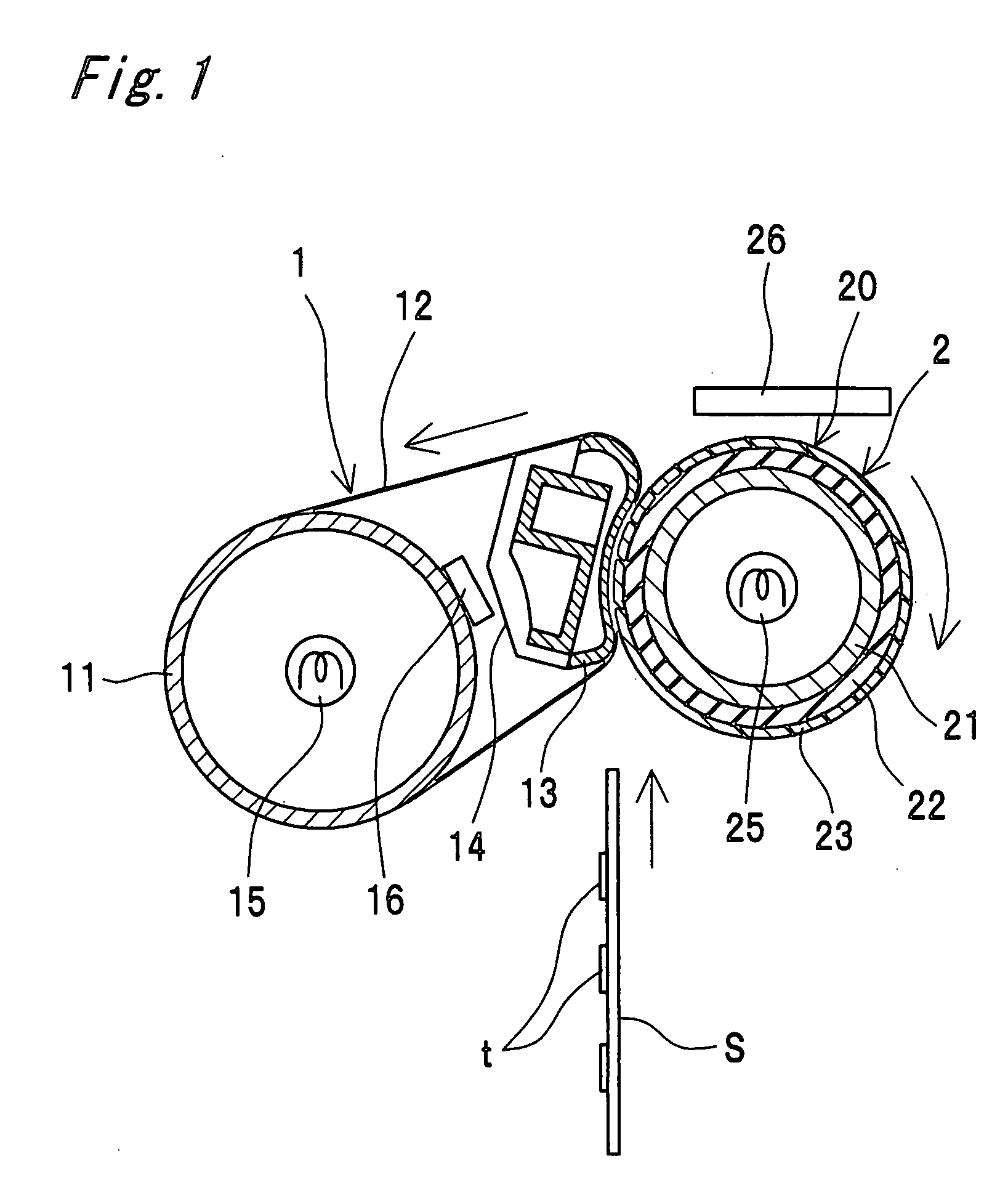
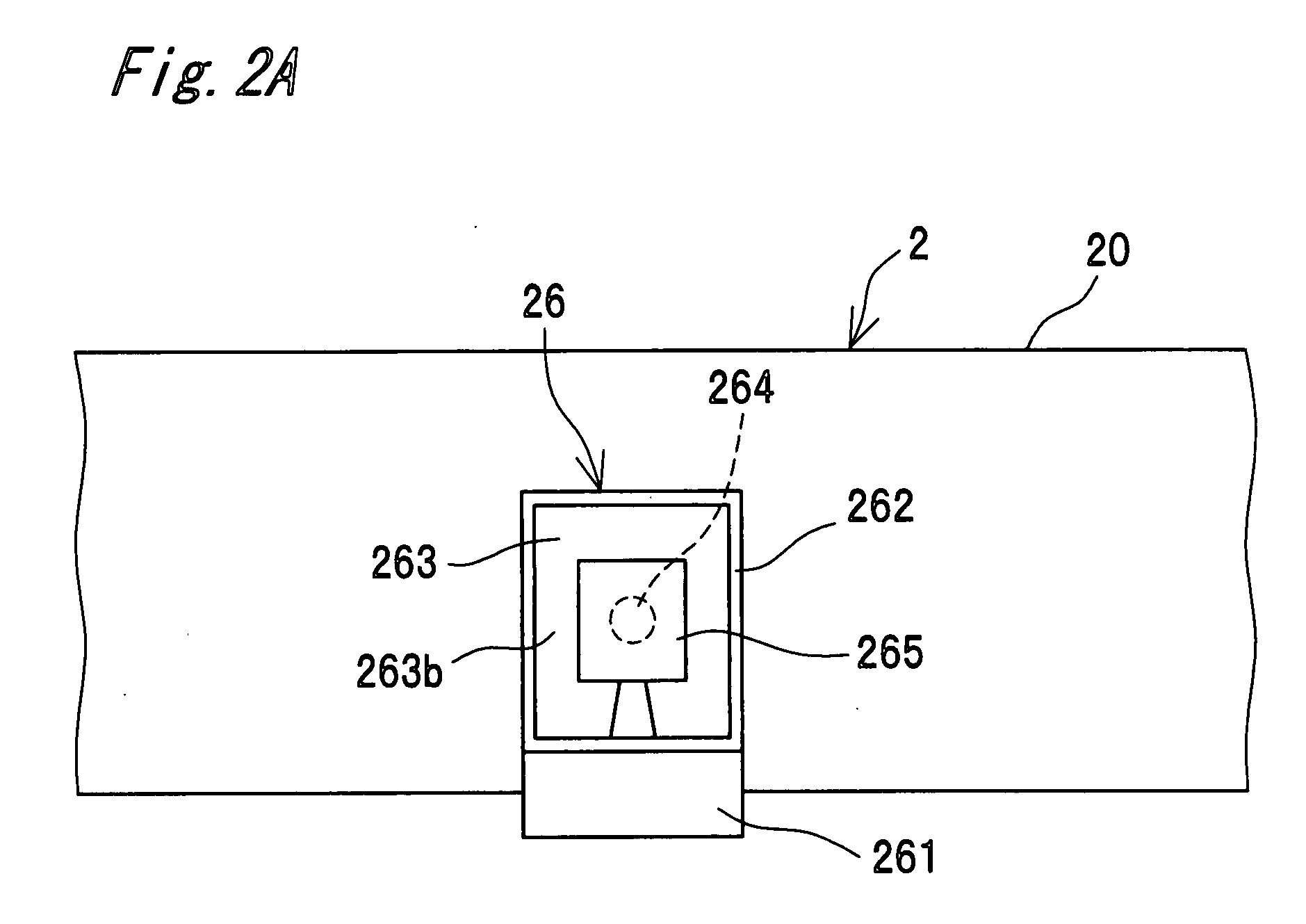
[0065]FIG. 3 shows a second embodiment of the temperature detecting device of the present invention. The second embodiment differs from the first embodiment (FIG. 2B) in the shape of the pressure thermistor as compared with the temperature detecting device.
[0066]That is to say, in a pressure thermistor 126 of the second embodiment, the film 263 is retained on the upper surface of the retention part 262. Therefore, the film 263 becomes hard to peel off the retention part 262. It is noted that one surface 263a of the film 263 is a rough surface although not shown in FIG. 3.
third embodiment
[0067]FIG. 4 shows a third embodiment of the temperature detecting device of the present invention. The third embodiment differs from the first embodiment (FIG. 2B) in the shape of the pressure thermistor as compared with the temperature detecting device.
[0068]That is to say, in a pressure thermistor 226 of the third embodiment, the thermosensitive device 264 is attached to the one surface 263a of the film 263. Therefore, the thermosensitive device 264 can receive heat directly from the pressure roller 20. It is noted that the one surface 263a of the film 263 is a rough surface although not shown in FIG. 4.
PUM
 Abstract
Description
Claims
Application Information