Receiver and information processing method

a technology of information processing and receiver, applied in the field of receiver and information processing method, can solve the problems of complex system, cost increase possibility, complex system,

Inactive Publication Date: 2008-03-06
HITACHI LTD
View PDF3 Cites 13 Cited by
  • Summary
  • Abstract
  • Description
  • Claims
  • Application Information

AI Technical Summary

Benefits of technology

[0013]The above outlined technique allows for easy playback of the transport stream that is downloaded, for example, at a high or low transmission rate different from a bit rate used during the normal playback of content.

Problems solved by technology

The modifications on the sending side in turn require the receiving side to conform to the modified system, making the entire system complicated and giving rise to a possibility of cost increase.
Modifying the processing on the sending side as in JP-A-2002-16561 makes the system costly and complicated in terms of facility and configuration.

Method used


Image

  • Receiver and information processing method
  • Receiver and information processing method
  • Receiver and information processing method

Examples


embodiment 1

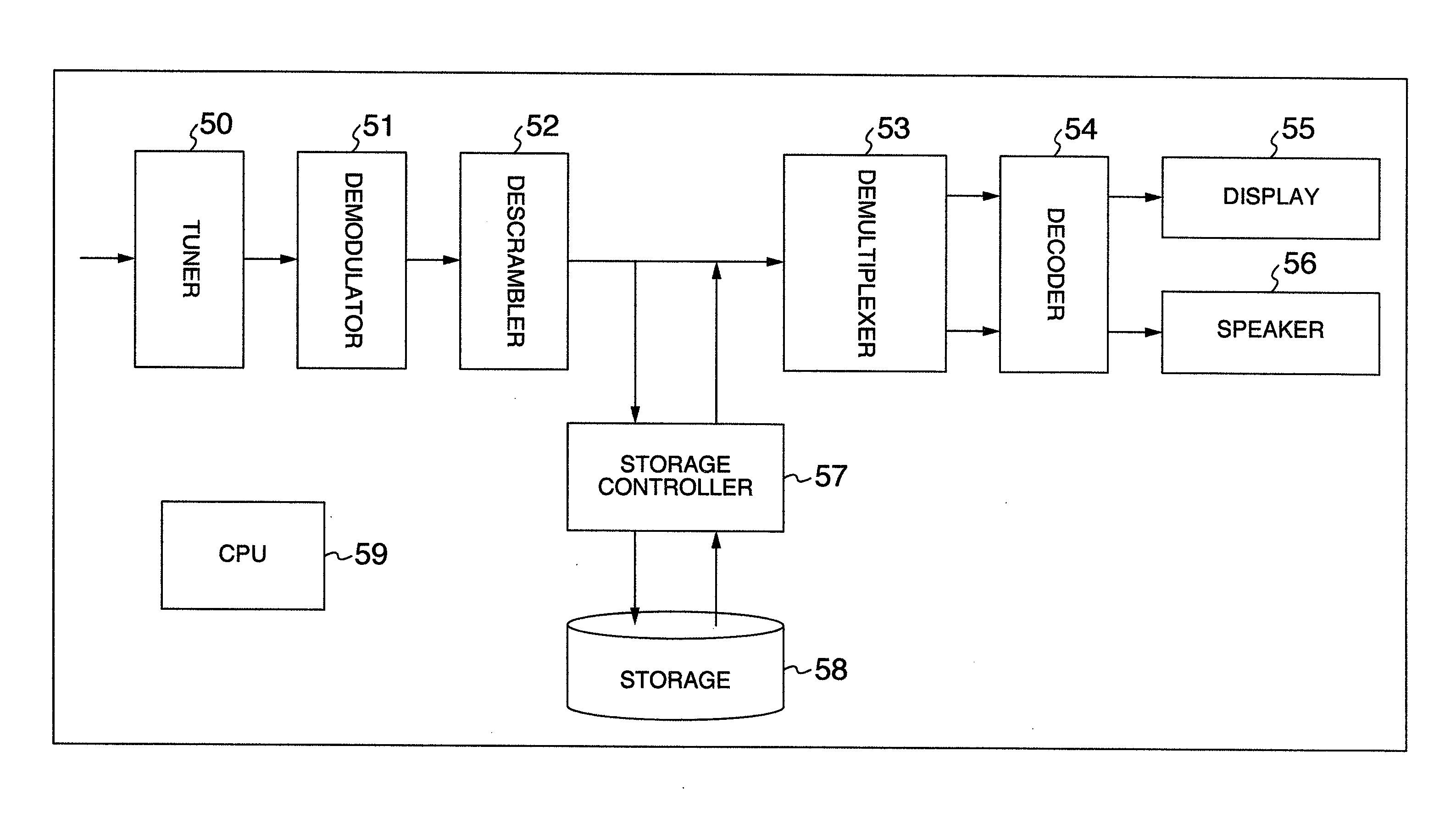
[0021]First, a basic concept of the receiver of embodiment 1 is explained. FIG. 5 shows a configuration of the receiver contemplated in this embodiment.

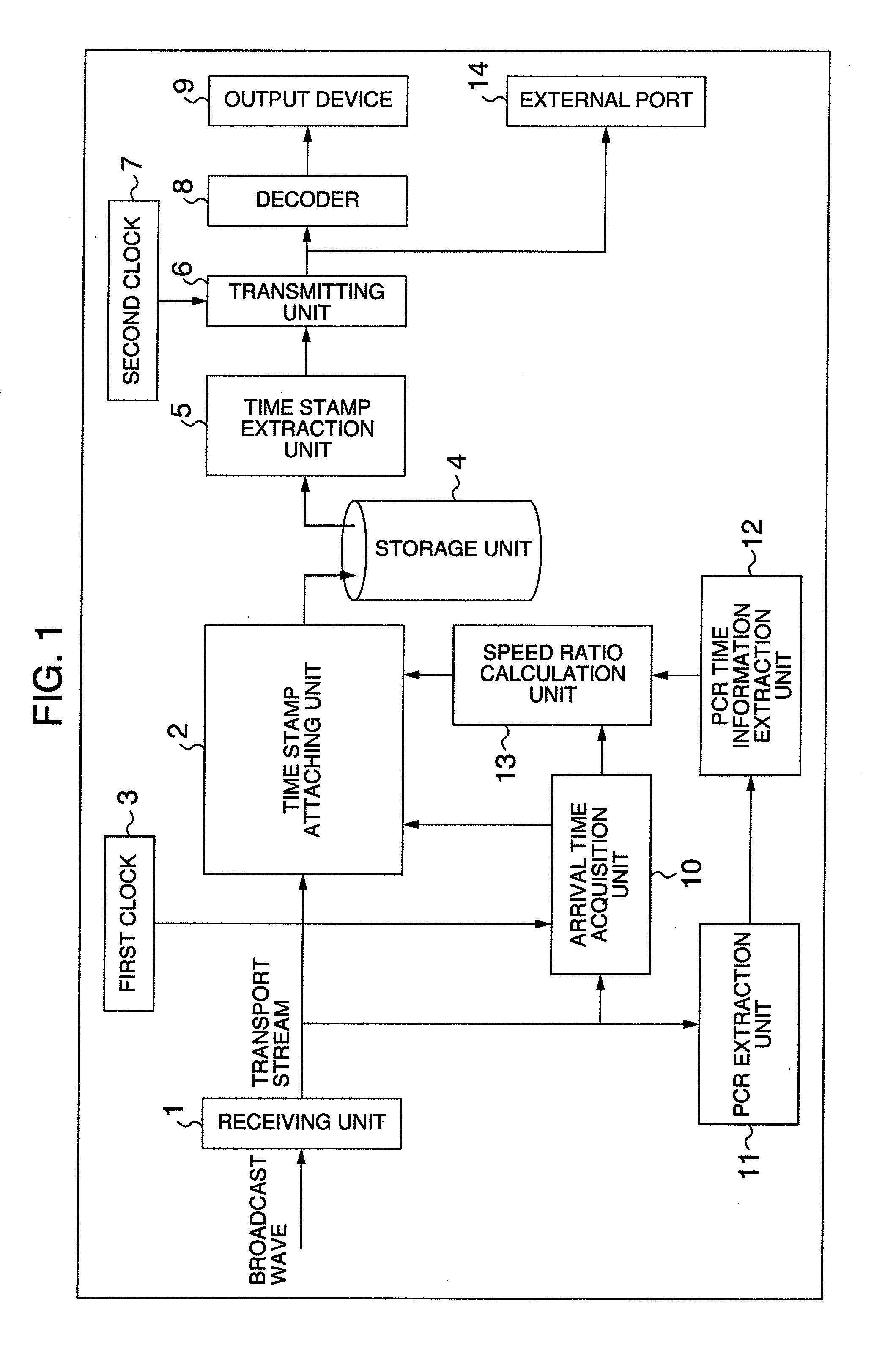
[0022]A broadcast signal is entered into a tuner 50, transformed into a transport stream by a demodulator 51 and decrypted by a descrambler 52. In the process of storing the stream, a storage controller 57 performs processing such as attaching a timestamp to the stream and records the time-stamped stream in a storage 58. During playback, a signal extracted from the storage 58 is transformed into a normal transport stream by the storage controller 57, which is then entered through a demultiplexer 53 into a video / audio decoder 54 where it is decoded, before being output to a display 55 and a speaker 56 as video and audio. CPU 59, though shown not to be wired to the respective blocks for simplicity, is actually connected to these blocks for their control. FIG. 1 is a block diagram showing functions required of the receiver in embodiment...

embodiment 2

[0057]Next, a second embodiment will be explained. As described above, the timestamp value on the ordinate in FIG. 3 is calculated from the packet arrival time on the abscissa and the speed ratio M determined from the immediately preceding two PCR's. There is, however, a possibility of errors being accumulated due to repetition of calculations, changes in transmission rate, and deviations of clocks referenced on the sending side and receiving side.

[0058]When, for example, PCR second packet has arrived, T20 as the timestamp value is calculated. There is a possibility that the calculated timestamp T20 may deviate from the time information TP2 recorded in the PCR second packet, which is the true time information for this packet during playback. In that case, T20 may be replaced with the value of TP2 to correct the error.

[0059]FIG. 4 is a flow chart showing an operation of embodiment 2. When a transport stream is entered, arrival time information of the transport stream packets is acqui...

embodiment 3

[0065]The preceding embodiment 1 has described an example case in which a transport stream that is transmitted over a broadcast wave is received as by a tuner 50. It is apparent that the similar effect can also be produced if, unlike embodiment 1, the transport stream is transmitted and received through communication lines such as the Internet at a speed different from the normal playback rate. In this case, the receiver is provided with a unit for receiving a communication line.

[0066]Further, in FIG. 1, it is apparent that the similar effect can also be produced if, during playback of data stored in the storage unit 4, the data as a content stream is sent at the normal playback rate from the transmitting unit 6 to other devices through the external port 14, rather than converting the data by the decoder 8 into video and audio and outputting them to the output device 9.

[0067]These embodiments may be said to be characterized in that they comprise a tuner to receive a transport stream...


PUM


Abstract

An object of this invention is to provide a receiver that downloads a transport stream at a bit rate different from the normal playback rate, attaches to the transport stream timestamps representing a playback timing for playback at the normal rate and then stores the time-stamped stream. When the receiver receives the transport stream at a transmission rate different from the normal playback rate and stores the stream, the receiver calculates timestamps representing a playback timing for playback at the normal rate according to the speed ratio of the received transport stream and attaches the timestamps to the transport stream before storing it as a time-stamped transport stream.

Description

INCORPORATION BY REFERENCE[0001]The present application claims priority from Japanese application JP2006-238444 filed on Sep. 4, 2006, the content of which is hereby incorporated by reference into this application.BACKGROUND OF THE INVENTION[0002]The present invention relates to a receiver and an information processing method which use digital content data such as videos and audios.[0003]Satellite and terrestrial digital broadcasting has come into widespread use in recent years and data broadcasting is also being used. Also, a data transmission service, so-called streaming, of digital content such as videos and audios has come to be used through wideband communication networks currently available to home.[0004]In these services, content such as videos and audios is compressed with MPEG system and transmitted in real time in the form of MPEG transport stream. A receiver checks a PCR packet, that is periodically inserted in the transport stream and has time information representing a ...

Claims


Application Information

Patent Timeline
Patent Type & Authority Applications(United States)
IPC IPC(8): H04N5/91G06F13/00H04N5/44H04N5/92H04N7/173H04N7/26H04N19/00H04N19/423H04N19/44H04N19/70H04N21/41H04N21/433
CPCG11B20/10009G11B20/10222G11B20/14G11B27/034H04N9/8205G11B27/3036H04N5/781H04N5/91G11B27/105
Inventor MIO, SATOSHI
Owner HITACHI LTD
Why Eureka
Try Eureka