Sheet retaining structure and printer for an electronic voting device

a technology of electronic voting and printers, applied in voting apparatus, thin material handling, instruments, etc., can solve the problems of inconvenient maintenance, huge effort of operators, and difficulty in maintaining the structure, so as to facilitate visual recognition, facilitate maintenance, and advance smoothly

Inactive Publication Date: 2008-03-06
SEIKO INSTR INC
View PDF10 Cites 0 Cited by
  • Summary
  • Abstract
  • Description
  • Claims
  • Application Information

AI Technical Summary

Benefits of technology

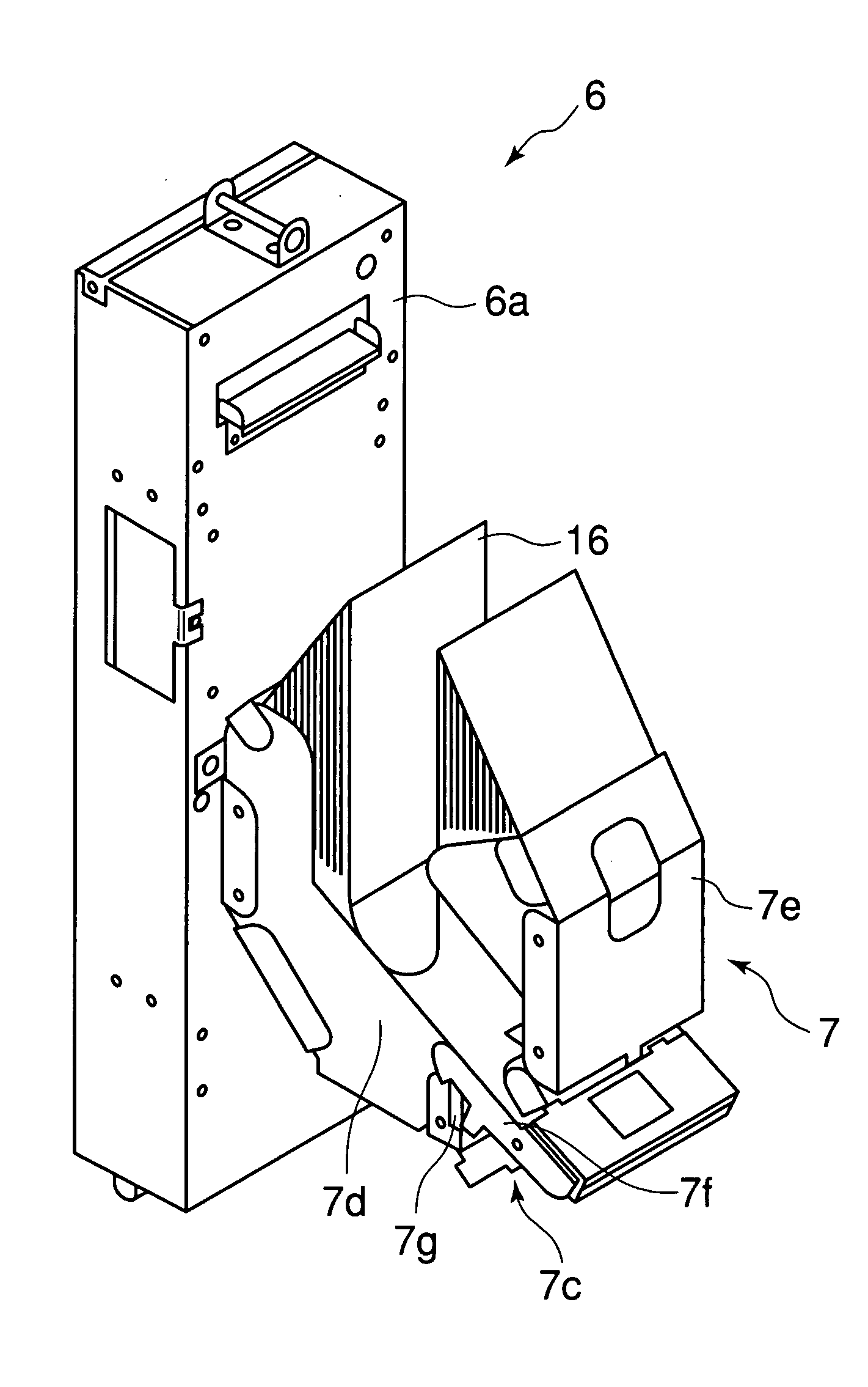
[0016]Note that, when one of the plurality of portions is a main body portion which can be mounted onto the casing, and the other portions are movable portions which can be opened and closed with respect to the main body portion, the casing of the printer and the container can be treated as a single unit. Therefore, attachment and detachment of the portions to and from the other members of the printer, and a maintenance operation can be easily performed.
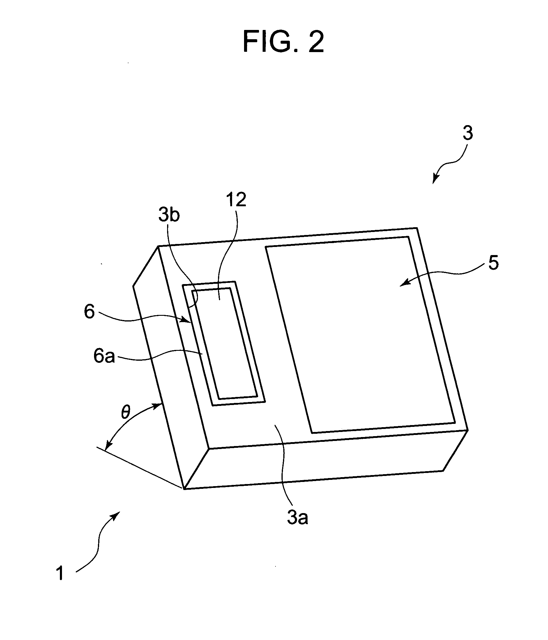
[0017]A printer for an electronic voting device according to the present invention includes: the sheet retaining structure described above; a printing portion, arranged in the casing, for performing printing on a part of the fanfold sheet supplied from the container; a cutter portion, arranged in the casing, for cutting off the part of the fanfold sheet, on which the printing is performed by the printing portion; a window portion, provided to a portion of the casing on a downstream side of the printing portion with respect to an advancing direction of the fanfold sheet, for allowing visual recognition of the part, on which the printing is performed, from an outside; and a discharge port, provided to a portion of the casing on the downstream side of the window portion with respect to the advancing direction of the fanfold sheet, for discharging the portion on which the printing is performed and which is cut off by the cutter portion.
[0018]In the printer, the fanfold sheet which is not curled unlike the rolled sheet is used as the recording sheet, so even when the leading end is the free end, the recording sheet can be allowed to smoothly advance for a long distance. Accordingly, even when, in order to facilitate visual recognition, the window portion is formed to be relatively large, a transporting mechanism (such as transport roller) for the recording sheet is not required in the window portion, so downsizing and thinning of the printer, and simplification of the structure thereof can be attained.
[0019]According to the present invention, the fanfold sheet is used as the recording sheet, so the sheet is not curled unlike the rolled sheet. Accordingly, even in the case where the leading end is the free end, the recording sheet can smoothly advance for a long distance. As a result, in the window portion enabling visual recognition of the printed results from the outside, it is not required to provide the transporting mechanism such as a roller for supporting and transporting the recording sheet, so downsizing and thinning of the printer, and simplification of the structure thereof can be attained.
[0020]Further, according to the present invention, it is possible to suppress increase in transport load due to the own weight of the fanfold sheet. In particular, in the upper layer portion of the fanfold sheet to be drawn out to the outside of the container, the transport load due to its own weight is alleviated, so the fanfold sheet can be relatively smoothly drawn out from beginning to end. Moreover, it is possible to reduce a space occupied by the container in the longitudinal direction of the fanfold sheet to be small.
[0021]Further, in the present invention, an operation of inserting the fanfold sheet into the container is extremely easily performed, and in the container, such a state can be easily transferred to a state where the fanfold sheet is retained while being deflected to a larger degree.

Problems solved by technology

Therefore, it takes time for summation and confirmation of results of the vote counting, and effort of operators is enormous.
Therefore, by viewing the rolled sheet which is reeled, the voting content can be known according to the order of the voters, thereby causing a problem from a perspective of privacy.
The rolled sheet is retained in a roll form, thereby causing curling.
Further, a leading end thereof is a free end, so it is difficult to smoothly transport the rolled sheet for a long distance in the window portion.
Thus, it is necessary to provide the plurality of transport rollers in the window portion, thereby resulting in complication and increase in size and costs of the structure of the electronic voting device including the printer.

Method used


Image

  • Sheet retaining structure and printer for an electronic voting device
  • Sheet retaining structure and printer for an electronic voting device
  • Sheet retaining structure and printer for an electronic voting device

Examples


second embodiment

[0064]Next, a description will be made of the other embodiments of the present invention schematically shown in FIGS. 10A-10C to 12A-12C. A container 17 according to the present invention shown in FIGS. 10A-10C includes a pair of movable portions 17a and 17b connected to each other through intermediation of a hinge mechanism 17c so as to be capable of opening and closing. Accordingly, as shown in FIG. 10A, the fanfold sheet 16 in a substantially flat state can be inserted in a state where the pair of movable portions 17a and 17b are opened with respect to each other. Next, as shown in FIG. 10B, by realizing a state where the movable portions 17a and 17b are closed with respect to each other, the fanfold sheet 16 can be retained while being deflected in the U-shape. After that, as shown in FIG. 10C, one movable portion 17a of the movable portions may be attached to the casing 6a, and the uppermost portion of the fanfold sheet 16 may be drawn out and inserted into the casing 6a to be ...

third embodiment

[0065]A container 18 according to the present invention shown in FIGS. 11A-11C has a structure in which to both sides of a main body portion 18a, movable portions 18b and 18c are connected through intermediation of each of hinge mechanisms 18d. As shown in FIG. 11A, in a state where the movable portions 18b and 18c are opened with respect to the main body portion 18a, the fanfold sheet 16 in the substantially flat state can be inserted. After that, as shown in FIG. 11B, by closing the movable portions 18b and 18c with respect to the main body portion 18a, the fanfold sheet 16 can be retained while being deflected in the U-shape. In this manner, in a state where the fanfold sheet 16 is retained in the container 18 while being deflected in the U-shape, as shown in FIG. 11C, the movable portion 18b may be attached to the casing 6a, and the uppermost portion of the fanfold sheet 16 is drawn out and inserted into the casing 6a to be set therein. With this structure, at the time of insert...


PUM


Abstract

In order to provide a printer for an electronic voting device, capable of smoothly transporting a recording sheet having a free end and capable of realizing downsizing and simplification, a container (7) includes a main body portion (7d) mounted on to a casing (6a) of a printer (6) and a movable portion (7e) attached to the main body portion (7d) so as to be capable of being opened and closed. In a state where the container (7) is opened, a fanfold sheet (16) in a state where a deflection thereof is small is inserted as it is, and the movable portion (7e) is then closed with respect to the main body portion (7d). As a result, the fanfold sheet (16) is retained in the container (7) in a state where the fanfold sheet (16) is largely deflected in a U-shape. The fanfold sheet (16) can smoothly be supplied from the container (7) into the casing (6a) The printer (6) prints electronic voting contents on the fanfold sheet (16) which is smoothly supplied. When the printed content is visually confirmed, the printer (6) prints characters indicating approval thereof. After that, a printed portion of the fanfold sheet (16) is cut off to be discharged.

Description

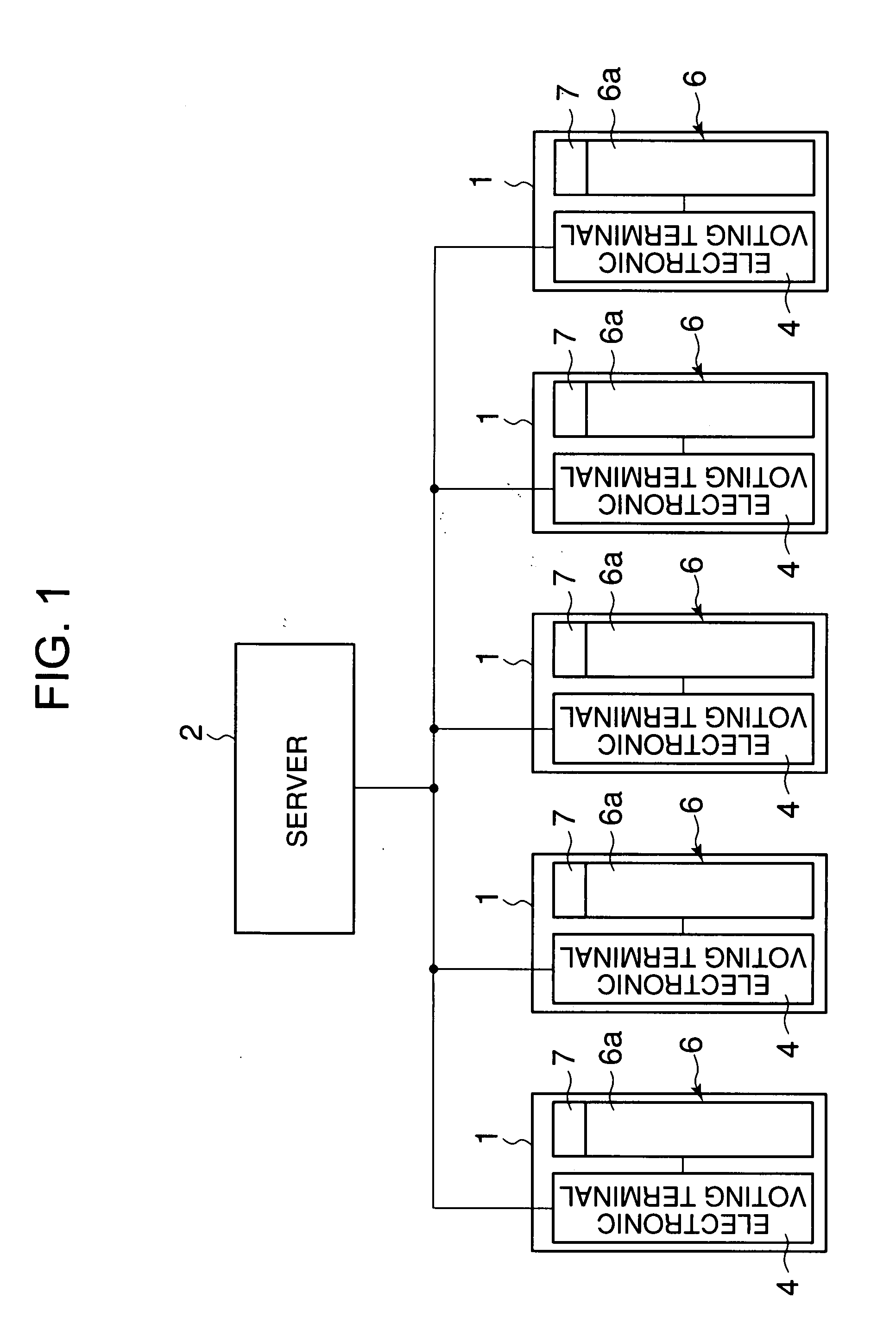
BACKGROUND OF THE INVENTION[0001]1. Field of the Invention[0002]The present invention relates to a sheet retaining structure and a printer for an electronic voting device including the same.[0003]2. Description of the Related Art[0004]Conventional election in municipalities or the like has been performed in such a manner that voters write person's name or the like on voting sheets and put the voting sheets in a ballot box. Vote counting is performed in such a manner that the ballot box is opened in the presence of an election official, the voting sheets are taken out and, the voting sheets are visually read one by one and summed up. In this manner, the conventional election is performed completely manually. Therefore, it takes time for summation and confirmation of results of the vote counting, and effort of operators is enormous.[0005]Here, in recent years, electronic voting using computers begins to be adopted. A basic structure of an electronic voting system includes electronic v...

Claims


Application Information

Patent Timeline
Patent Type & Authority Applications(United States)
IPC IPC(8): B41J11/66
CPCB41J11/58G07C13/00B65H2701/11231B65H16/00
Inventor NUREKI, SHINJIMATSUDA, MAKOTOHOSHIDA, TOMOHIKOSEINO, TAKUMI
Owner SEIKO INSTR INC
Why Eureka
Try Eureka