
Control device and control method for vehicle

a control device and control method technology, applied in the direction of mechanical equipment, digital data processing details, instruments, etc., can solve the problems of inability to execute control that allows the loose engagement of frictional engagement members, and the inability to reduce the shock generated by the engagement of frictional engagement elements, so as to prevent unnecessary control

Inactive Publication Date: 2008-03-06
TOYOTA JIDOSHA KK
View PDF3 Cites 9 Cited by
  • Summary
  • Abstract
  • Description
  • Claims
  • Application Information

AI Technical Summary

Benefits of technology

[0011]The present invention provides a control device and a control method for a vehicle capable of preventing an unnecessary control.
[0017]As described above, the error determination unit determines whether the detection unit, which detects the position of the transmission selection member, is functioning normally. If it is determined that the detection unit is malfunctioning, it is not possible to accurately detect the position of the transmission selection member and, therefore, it is not possible to determine whether the gear step is normal or abnormal based on the time that has elapsed since the manipulation had been switched from the drive position to the neutral position. Accordingly, when it is determined that the detection unit is malfunctioning, the determination unit is prohibited from determining whether the gear step is abnormal. As a result, a mistaken determination can be avoided.

Problems solved by technology

On the other hand, when the manipulation is rapidly moved, the control that allows the loose engagement of the frictional engagement members may not be executed.
However, when the frictional engagement elements are engaged, the control that reduces the shock generated by the engagement of the frictional engagement elements are not executed.

Method used


Image

  • Control device and control method for vehicle
  • Control device and control method for vehicle
  • Control device and control method for vehicle

Examples


Embodiment Construction

[0028]Hereinafter, example embodiments of the present invention will be described in detail with reference to the accompanying drawings. In the following description, like parts are represented by like reference numerals. The like parts have like names and like functions. Therefore, redundant description thereof will be omitted.

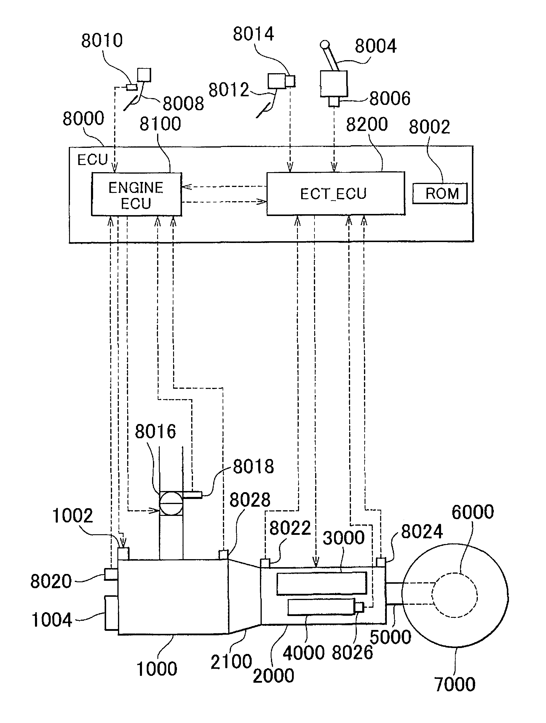
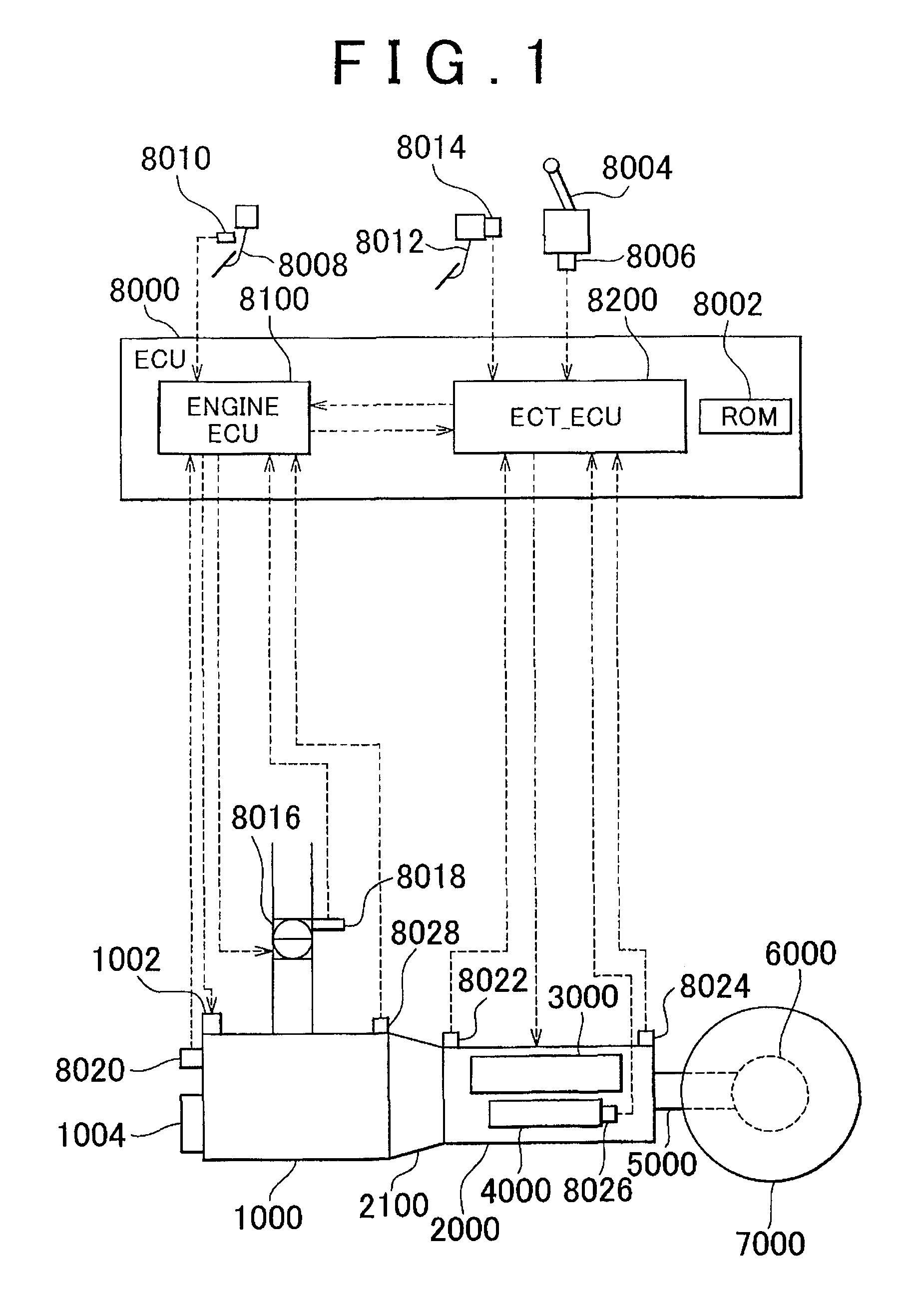
[0029]A vehicle equipped with a control device in accordance with an embodiment of the present invention will be described with reference to FIG. 1. In this embodiment, the vehicle is an FR (front engine rear drive) vehicle, but it may be a vehicle other than an FR vehicle.

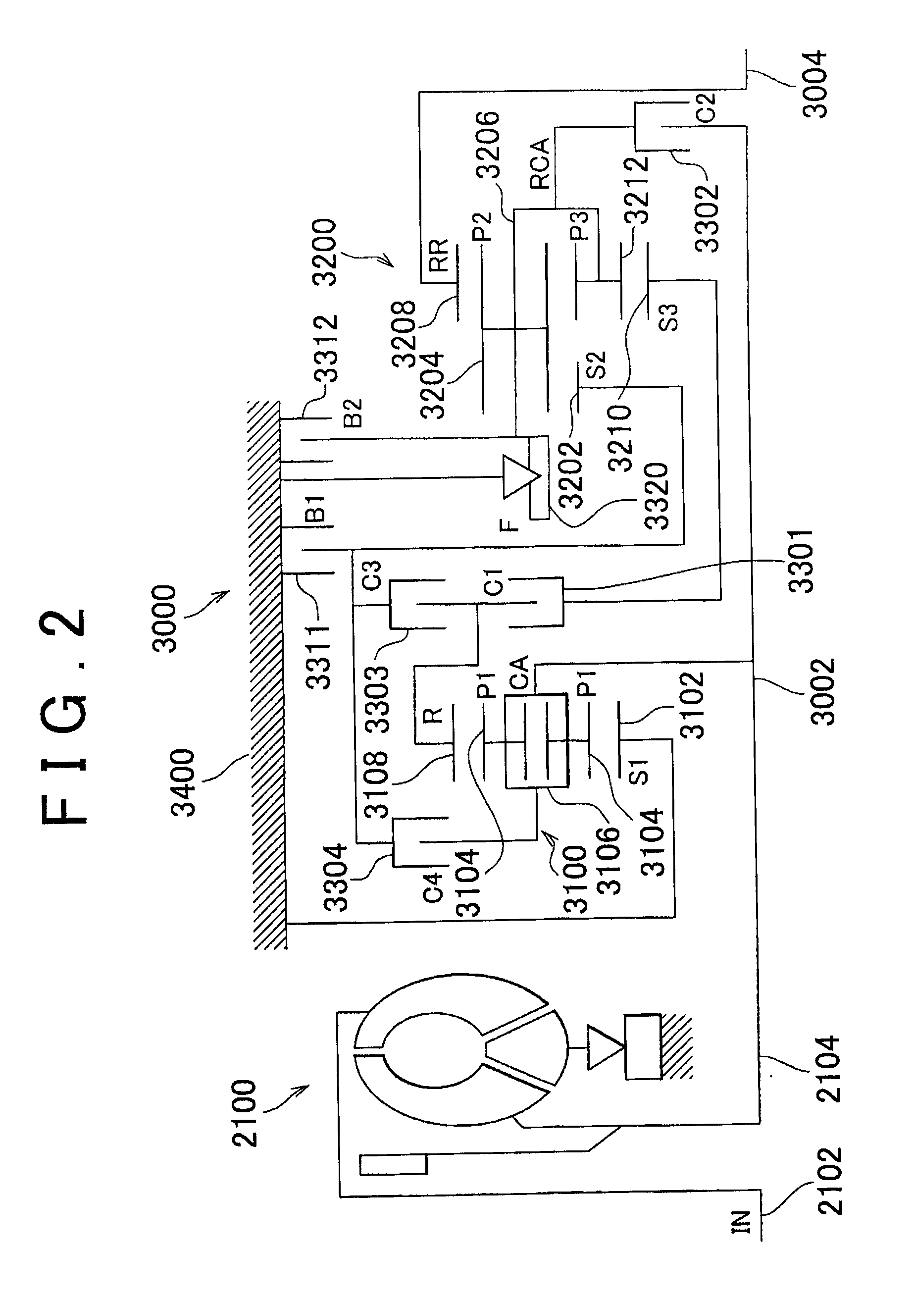
[0030]The vehicle includes an engine 1000, an automatic transmission 2000, a torque converter 2100, a planetary gear unit 3000 forming a part of the automatic transmission 2000, a hydraulic circuit 4000 forming a part of the automatic transmission 2000, a propeller shaft 5000, a differential gear 6000, rear wheels 7000, and an ECU (electronic control unit) 8000. The control device of this e...


PUM


Abstract

An ECU for a vehicle equipped with an automatic transmission includes a detection unit that detects a position of a transmission selection member manipulated by a driver; a determination unit that determines whether a gear step is abnormal when a preset time has elapsed after the transmission selection member is shifted from a drive position to a neutral position. The ECU further includes a control unit that controls the automatic transmission such that if the transmission selection member is shifted from the neutral position to the drive position when the gear step has been determined to be abnormal, a shock generated by the engagement of the frictional engagement elements is reduced.

Description

INCORPORATION BY REFERENCE[0001]The disclosure of Japanese Patent Application No. 2006-241387 filed on Sep. 6, 2006 including the specification, drawings and abstract is incorporated herein by reference in its entirety.BACKGROUND OF THE INVENTION[0002]1. Field of the Invention[0003]The present invention relates to a control device and a control method for a vehicle; and, more particularly, to a control device and a control method for a vehicle equipped with an automatic transmission that forms gear steps by engaging frictional engagement elements.[0004]2. Description of the Related Art[0005]In a conventional automatic transmission, gear steps are formed by engaging frictional engagement elements through the use of a hydraulic pressure supplied to the frictional engaging engagement elements. The automatic transmission forms a gear step according to a position of a shift lever. When the shift lever is in a drive (D) position, the hydraulic pressure is supplied to the frictional engage...

Claims


Application Information

Patent Timeline
IPC IPC(8): F16H61/12F16H59/04F16H61/68F16H61/684F16H61/686F16H63/50
CPCF16H59/105F16H61/12Y10T477/693638F16H2061/1284F16H2061/1224
Inventor KOBAYASHI, NOBUFUSASUGIMURA, TOSHIOASAMI, TOMOHIROTOKURA, TAKAAKI
Owner TOYOTA JIDOSHA KK
Learn More