Flow meter

a flow meter and flow rate technology, applied in the field of flow meters, can solve the problem of relatively high cost of electromagnetic flow meters, and achieve the effect of reducing costs

Active Publication Date: 2008-03-13
ABB LTD
View PDF26 Cites 5 Cited by
  • Summary
  • Abstract
  • Description
  • Claims
  • Application Information

AI Technical Summary

Benefits of technology

[0006] The present invention aims to provide at least an alternative type of electroma

Problems solved by technology

However, the cost of electromagnetic flow meters is relatively high mainly due

Method used


Image

  • Flow meter
  • Flow meter
  • Flow meter

Examples


embodiment 1

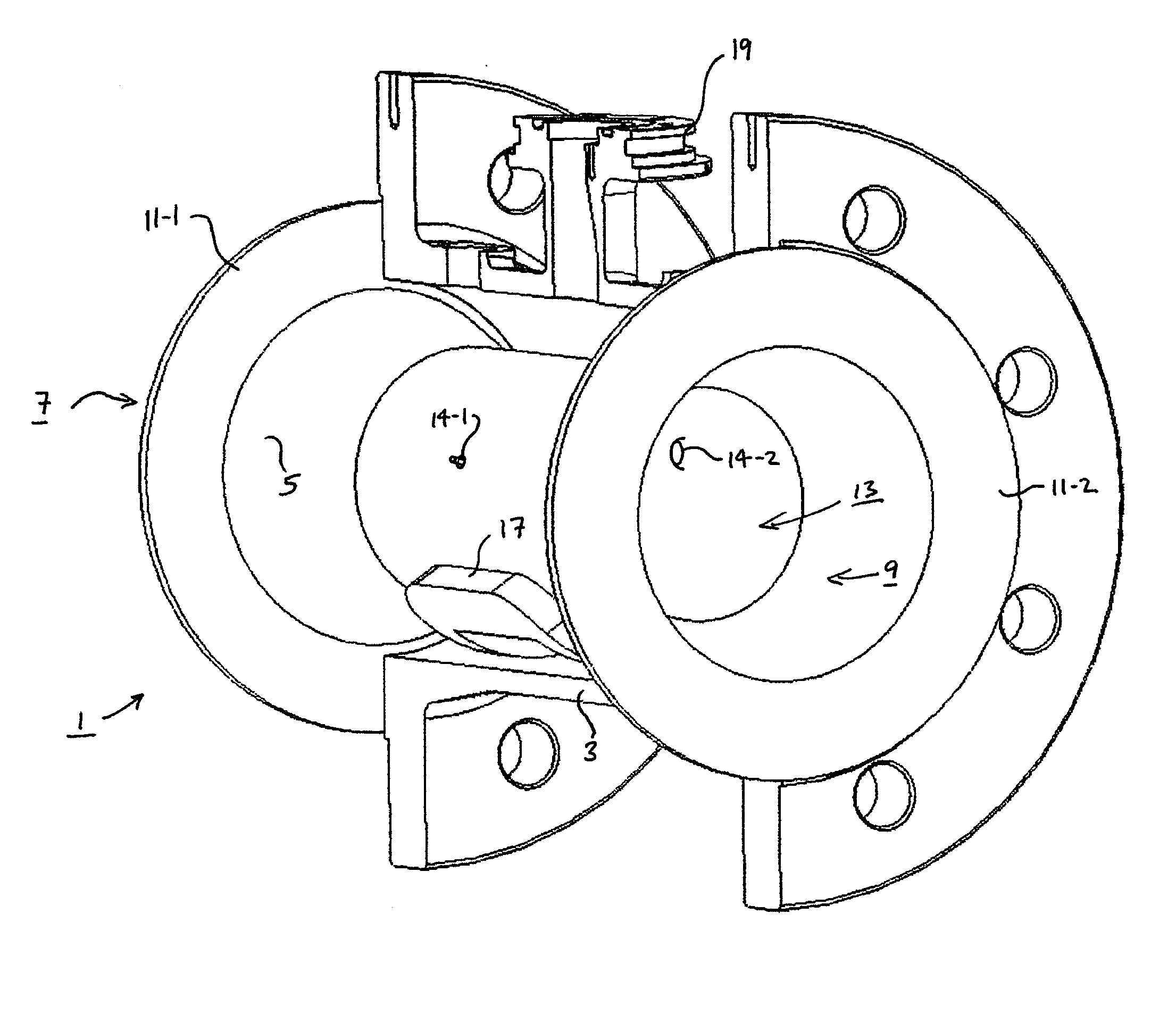
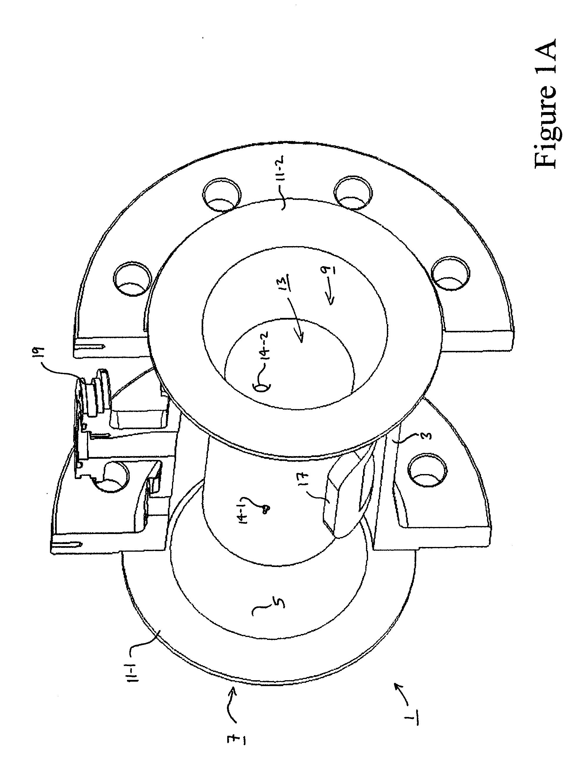
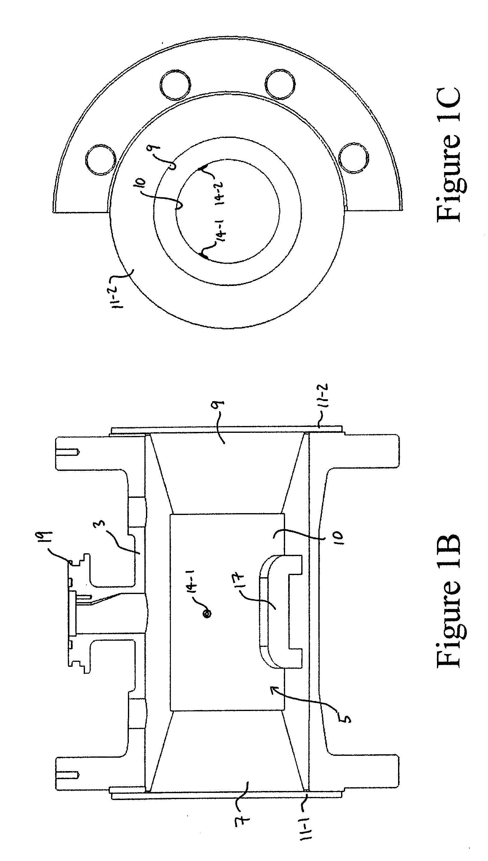
[0041]FIGS. 1 and 2 illustrate an electromagnetic flow meter 1 embodying the present invention. The flow meter 1 has a flow conduit 3 (made in this embodiment of Carbon Steel) which is cut in half to illustrate the form of an elongate insert 5 that is longitudinally inserted within the conduit 3. The insert 5 includes an inlet section 7, an outlet section 9 and a central measuring section 10, all of substantially circular cross-section. The dimensions of the inlet 7 and the outlet 9 are such that these sections of the insert 5 just fit within the flow conduit 3. In this embodiment, the insert has flanges 11-1 and 11-2 at each end (one of which may be detachable to facilitate insertion of the insert 5 within the flow conduit 3) that hold the insert securely within the flow conduit 3. The inner walls of the insert 3 define a central bore 13 for the passing of the fluid and means in the form of electrodes 14-1 and 14-2, for detecting electrical potential of the fluid passing through th...

second embodiment

[0049]FIGS. 3A, 3B and 3C illustrate an alternative design of electromagnetic flow meter embodying the present invention. In these Figures, the same reference numerals have been used to designate like elements.

[0050] The main difference between the flow meter of this embodiment and the flow meter of the first embodiment is that the measuring section 10 has an octagonal cross-section in a direction transverse to the fluid flow. Further, in this embodiment, as illustrated in FIG. 3B, the single coil 17 surrounds a lower segment of the measuring section 10 having a segment angle (θ) of approximately 140 degrees.

[0051] In this embodiment, each electrode 14 is offset from the centerline, by an offset angle (Φ) of 20 degrees.

[0052] In this embodiment, the insert may be made from any one of: polytetrafluoroethylene (PTFE), ethylene-tetrafluoroethylene (ETFE), polypropylene (PP), polyvinylchloride (PVC), polyethylene terephthalate (PET), acrylonitrile butadiene styrene (ABS), polyethylen...

third embodiment

[0053]FIGS. 4A and 4B illustrate an alternative design of electromagnetic flow meter embodying the present invention. In these Figures, the same reference numerals have been used to designate like elements. The only difference between the flow meter of this embodiment and the flow meter of the second embodiment is that in this embodiment, the electrodes 14 are not offset from the centerline. Instead, they are positioned to be opposite each other along the centerline that passes through the longitudinal axis of the measuring section 10.


PUM

PropertyMeasurementUnit
Fractionaaaaaaaaaa
Angleaaaaaaaaaa
Angleaaaaaaaaaa

Abstract

An electromagnetic flow meter for measuring flow rate of a fluid passing therethrough includes a conduit defining a fluid inlet, a fluid outlet and a measuring section positioned between the inlet and the outlet. The flow meter also includes a single coil for generating a magnetic field across the measuring section and electrodes for detecting induced electrical potential due to the fluid passage. The coil may be arranged to surround a section of the measuring section over a segment angle of between 140 and 180 degrees. The electrodes may be positioned so that they are offset from being opposite each other on the centerline of the measuring section, by an offset angle of between 5 degrees and 45 degrees.

Description

CROSS-REFERENCE TO RELATED APPLICATIONS [0001] This application claims priority of Great Britain Application No. 0616504.7, filed Aug. 18, 2006, which is hereby incorporated herein in its entirety by reference. FIELD OF THE INVENTION [0002] The present invention relates to flow meters and in particular to electromagnetic flow meters and the manufacture thereof. BACKGROUND OF THE INVENTION [0003] Electromagnetic flow meters, and their modes of operation, are well known. In use, an electromagnetic field is generated whose lines of flux are mutually perpendicular to the longitudinal axis of the flow tube through which the fluid to be metered is conducted and to the transverse axis along which the electrodes are located at diametrically opposed positions with respect to the tube. The operating principles are based on Faraday's Law of induction, which states that the voltage induced across any conductor as it moves at right angles through a magnetic field will be proportional to the velo...

Claims


Application Information

Patent Timeline
IPC IPC(8): G01F1/58H01F7/06
CPCY10T29/4902G01F1/586
Inventor LINCOLN, DAVIDARMITAGE, MICHAEL
Owner ABB LTD
Why Eureka
Try Eureka