Energy collecting system

a technology of energy collection and energy storage, applied in the direction of photovoltaics, electrical appliances, semiconductor devices, etc., can solve the problems of large space, time-consuming and labor-intensive launch, fragile light collector plates, etc., and achieve the effect of optimizing solar energy collection

Inactive Publication Date: 2008-03-13
DELTA ELECTRONICS INC
View PDF10 Cites 21 Cited by
  • Summary
  • Abstract
  • Description
  • Claims
  • Application Information

AI Technical Summary

Benefits of technology

[0012]One embodiment of an energy collecting system of the present invention includes a substrate; a photosensitive layer selectively disposed on the substrate; and at least a convex lens disposed on the photosensitive layer. The convex lens has semi-spheroid, thinner semi-spheroid, semi-columned or thinner semi-columned shape. The convex lenses are arranged in an array over the substrate, and are coated with an antireflection layer. Sunlight can be focused onto the photosensitive layer via refraction from the convex lens. Accordingly, sunlight can reach the photosensitive layer through a simplified refraction path, optimizing collection of solar energy.

Problems solved by technology

The device, however, occupies a large space and takes time to be launched because of its large volume and complex structure.
The light collector plate, however, is fragile and manufacture thereof is not easy.
Conversion efficiency of sunlight, however, may degrade because incident angle of sunlight is limited to reflection surfaces of adjacent tilted reflection mirrors.

Method used


Image

  • Energy collecting system
  • Energy collecting system
  • Energy collecting system

Examples


Embodiment Construction

[0030]The following description is of the best-contemplated mode of carrying out the invention. This description is made for the purpose of illustrating the general principles of the invention and should not be taken in a limiting sense. The scope of the invention is best determined by reference to the appended claims.

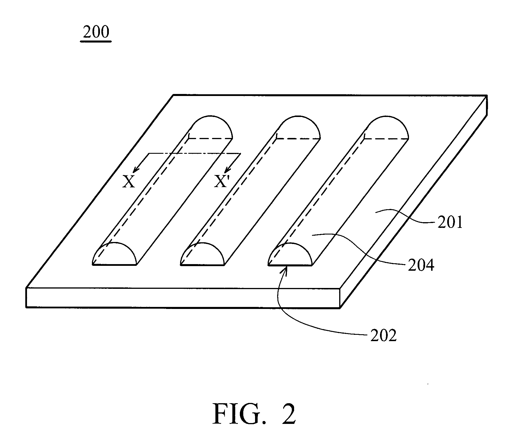
[0031]FIG. 2 is a schematic view showing an embodiment of the energy collecting system according to the present invention. An energy collecting system 200 includes a substrate 201, a photosensitive layer 202 and a plurality of convex lenses 204. The photosensitive layer 202 is disposed on the substrate 201, and the convex lenses 204 are on the photosensitive layer 202. In this embodiment, the photosensitive layer 202 is selectively disposed on the substrate 201. Note that the photosensitive layer 202 does not have to be disposed all over the substrate 201; more specifically, the pertinent aspect is that the photosensitive layer 202 is between the convex lenses 204 and ...


PUM


Abstract

The invention discloses an energy collecting system comprising a substrate; a photosensitive layer selectively disposed on the substrate; and at least one convex lens disposed on the photosensitive layer. The shape of the convex lens is a semi-spheroid, thinner semi-spheroid, semi-columned, or thinner semi-columned shape. The convex lenses are arranged in an array order and are coated with an anti-reflection layer.

Description

BACKGROUND OF THE INVENTION[0001]1. Field of the Invention[0002]The present invention relates to an energy collecting system and in particular, to an energy collecting system which collects solar energy and is capable of enhancing the photoelectric conversion efficiency.[0003]2. Description of the Related Art[0004]A solar collector receives solar energy using photovoltaic cells and converts it to electricity. The photovoltaic cell can be a single-leveled or a multi-leveled structure.[0005]In U.S. Pat. No. 6,399,874, a disclosed single-leveled square (7mm×7 mm) photovoltaic cell collects energy from the sunlight utilizing a Fresnel lens.[0006]Higher photoelectric conversion efficiency can be achieved employing a solar cell with a multi-leveled structure. In U.S. Pat. No. 6,881,893, for example, a device disclosed employing a magnifying lens for focusing the light. The magnifying lens is disposed at the center of a circular plate which serves as a cover of a collection unit of the dev...

Claims


Application Information

Patent Timeline
Patent Type & Authority Applications(United States)
IPC IPC(8): H01L31/052
CPCY02E10/52H01L31/0232H01L31/0543H02S40/22
Inventor HO, FANG-CHUANLIN, KUNG-UEHCHEN, YANG-LIN
Owner DELTA ELECTRONICS INC
Why Eureka
Try Eureka