Operating piece unit for switch and electronic apparatus

a technology of electronic equipment and operating piece, applied in the field of electronic equipment, can solve problems such as deteriorating assembly efficiency, and achieve the effect of simplifying assembly of electronic equipmen

Inactive Publication Date: 2008-03-13
FUJITSU CLIENT COMPUTING LTD
View PDF6 Cites 15 Cited by
  • Summary
  • Abstract
  • Description
  • Claims
  • Application Information

AI Technical Summary

Benefits of technology

[0013]According to a third aspect of the present invention, there is provided a switch comprising: an operating piece; a connecting piece opposed to the operating piece at a predetermined interval; a sliding piece extending around a space defined between the operating piece and the connecting piece, the sliding piece connecting the upper end of the operatin

Problems solved by technology

This results in a deteriorate

Method used


Image

  • Operating piece unit for switch and electronic apparatus
  • Operating piece unit for switch and electronic apparatus
  • Operating piece unit for switch and electronic apparatus

Examples


Embodiment Construction

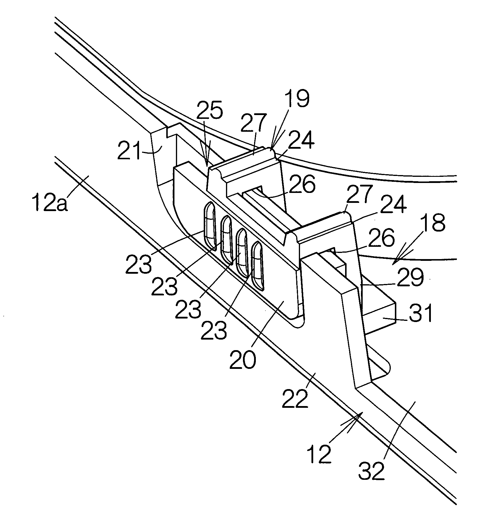
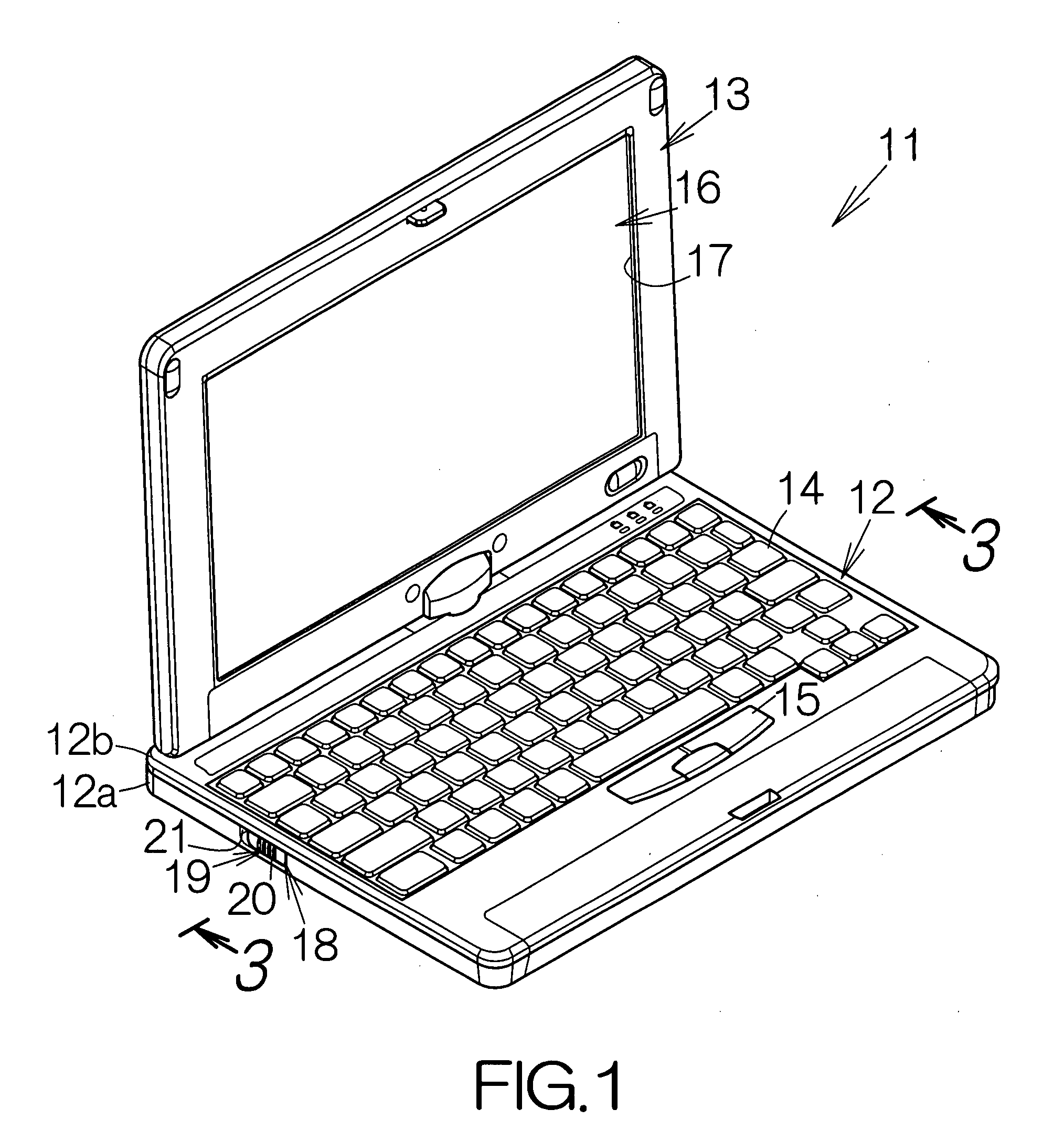
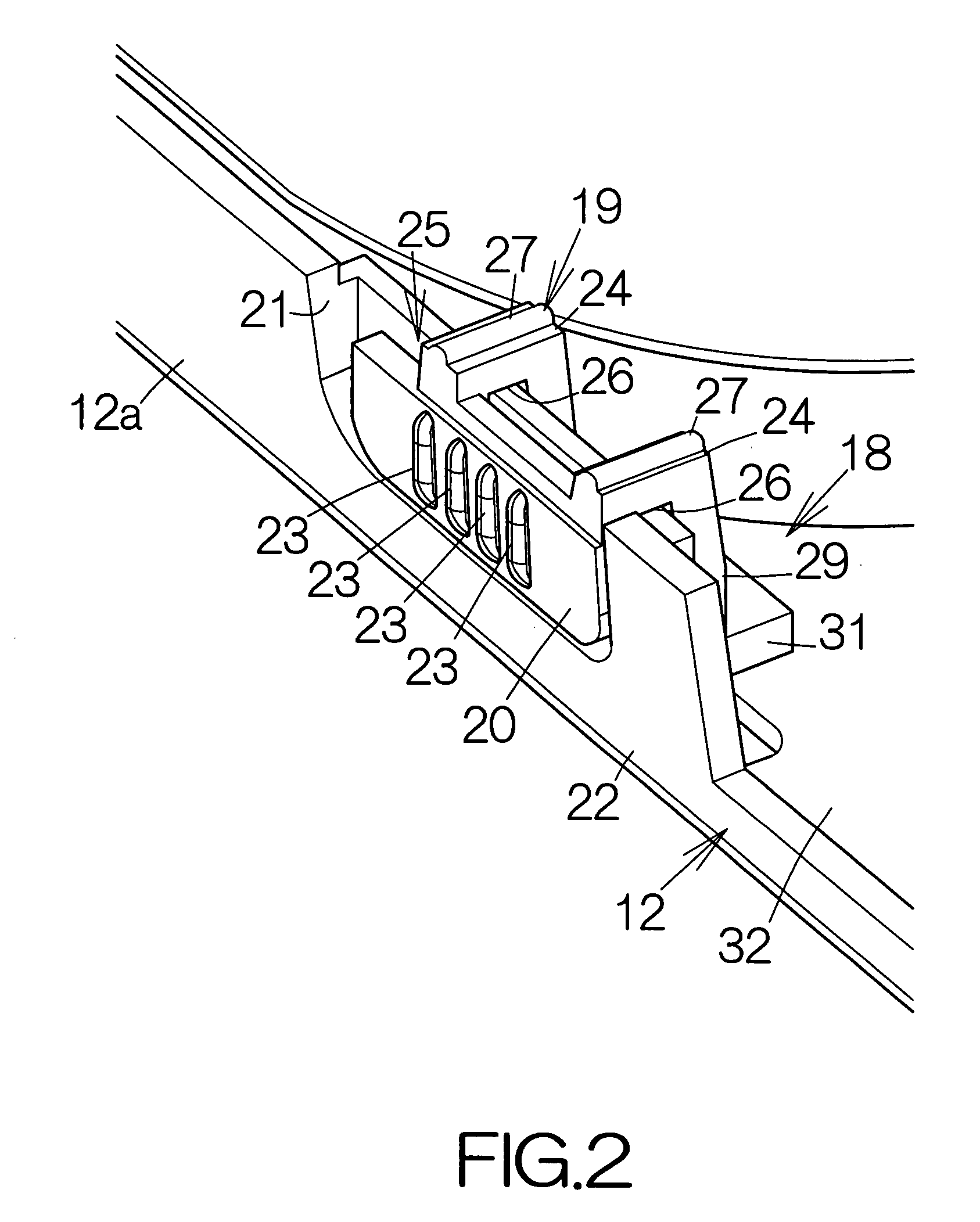
[0021]FIG. 1 schematically illustrates a notebook personal computer 11 as a specific example of an electronic apparatus according to the present invention. The notebook personal computer 11 includes a thin first enclosure, namely a main body enclosure 12, and a second enclosure, namely a display enclosure 13. The display enclosure 13 is coupled to the main body enclosure 12 for a relative swinging movement. The main body enclosure 12 includes a base 12a and a cover 12b removably coupled to the base 12a. Input devices such as a keyboard 114 and a pointing device 15 are embedded in the surface of the cover 12b. Users manipulate the keyboard 14 and / or the pointing device 15 to input commands and / or data.

[0022]A liquid crystal display (LCD) panel module 16 is enclosed in the display enclosure 13, for example. The screen of the LCD panel module 16 exposes within a window opening 17 defined in the display enclosure 13. Texts and graphics appear on the screen. Users can see the ongoing ope...


PUM


Abstract

A switch element is enclosed in the enclosure. The switch element includes a movable piece designed to move along a straight line between a switch-on position and a switch-off position. An operating piece is located along the outer surface of the enclosure. A connecting piece is located along the inner surface of the enclosure. The connecting piece is connected to the movable piece of the switch element. A sliding piece extends around the edge of the enclosure to connect one end of the operating piece to one end of the connecting piece. The sliding piece is designed to slide on the edge of the enclosure. The movable piece of the switch element moves between the switch-on position and the switch-off position in response to the movement of the operating piece.

Description

BACKGROUND OF THE INVENTION[0001]1. Field of the Invention[0002]The present invention relates to an electronic apparatus such as a notebook personal computer.[0003]2. Description of the Prior Art[0004]A switch is incorporated in a notebook personal computer as disclosed in Japanese Patent Application Publication No. 10-154428, for example. The switch includes an operating piece attached to the side surface of the enclosure of the notebook personal computer for relative sliding movement. The operating piece is connected to a switch element located in the enclosure through a connecting piece. The connecting piece penetrates through a through hole defined in the wall of the enclosure. The switch element moves between an switch-on position and an switch-off position through the sliding movement of the operating piece.[0005]The connecting piece is inserted in the through hole during the assembly of the notebook personal computer. A protrusion and / or a rib are formed on the connecting pie...

Claims


Application Information

Patent Timeline
IPC IPC(8): H01H1/36
CPCH01H15/107H01H2221/014H01H2217/024
Inventor IIJIMA, TAKASHI
Owner FUJITSU CLIENT COMPUTING LTD
Why Eureka
Try Eureka