Portable charging device capable of outputting voltage

Inactive Publication Date: 2008-03-13
LU SHENG FU
View PDF2 Cites 30 Cited by
  • Summary
  • Abstract
  • Description
  • Claims
  • Application Information

AI Technical Summary

Benefits of technology

[0006]By means of the above-mentioned device, the present invention can overcome the conventional drawbacks and is capable of reducing t

Problems solved by technology

However, different countries have different voltage specifications and the charger cannot be applied for charging at any place.
As a result, it is still not convenient enough.
However, it is still imperfect since its usage is restricted to the inside of the

Method used


Image

  • Portable charging device capable of outputting voltage
  • Portable charging device capable of outputting voltage
  • Portable charging device capable of outputting voltage

Examples


Embodiment Construction

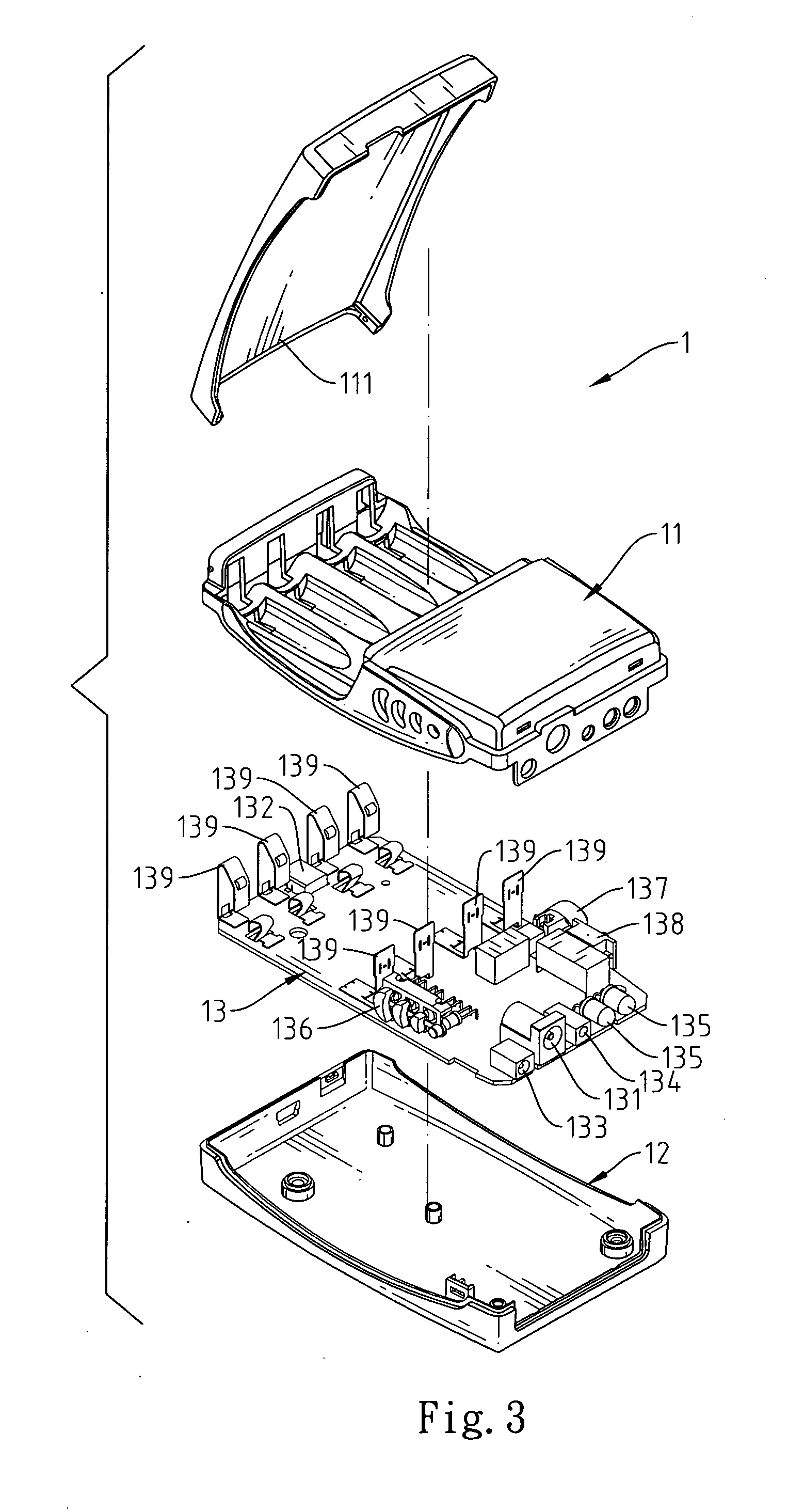
[0015]Referring to FIGS. 1 through 3 and 6, a portable charging device capable of outputting voltage of the present invention is capable of charging rechargeable batteries, and comprises a charger base 1, a power supply 2 and a solar panel 3. In accordance with a preferred embodiment, the portable charging device is applied for charging four rechargeable batteries 4, which are divided into two groups including a first rechargeable battery group 42 and a second rechargeable battery group 41.

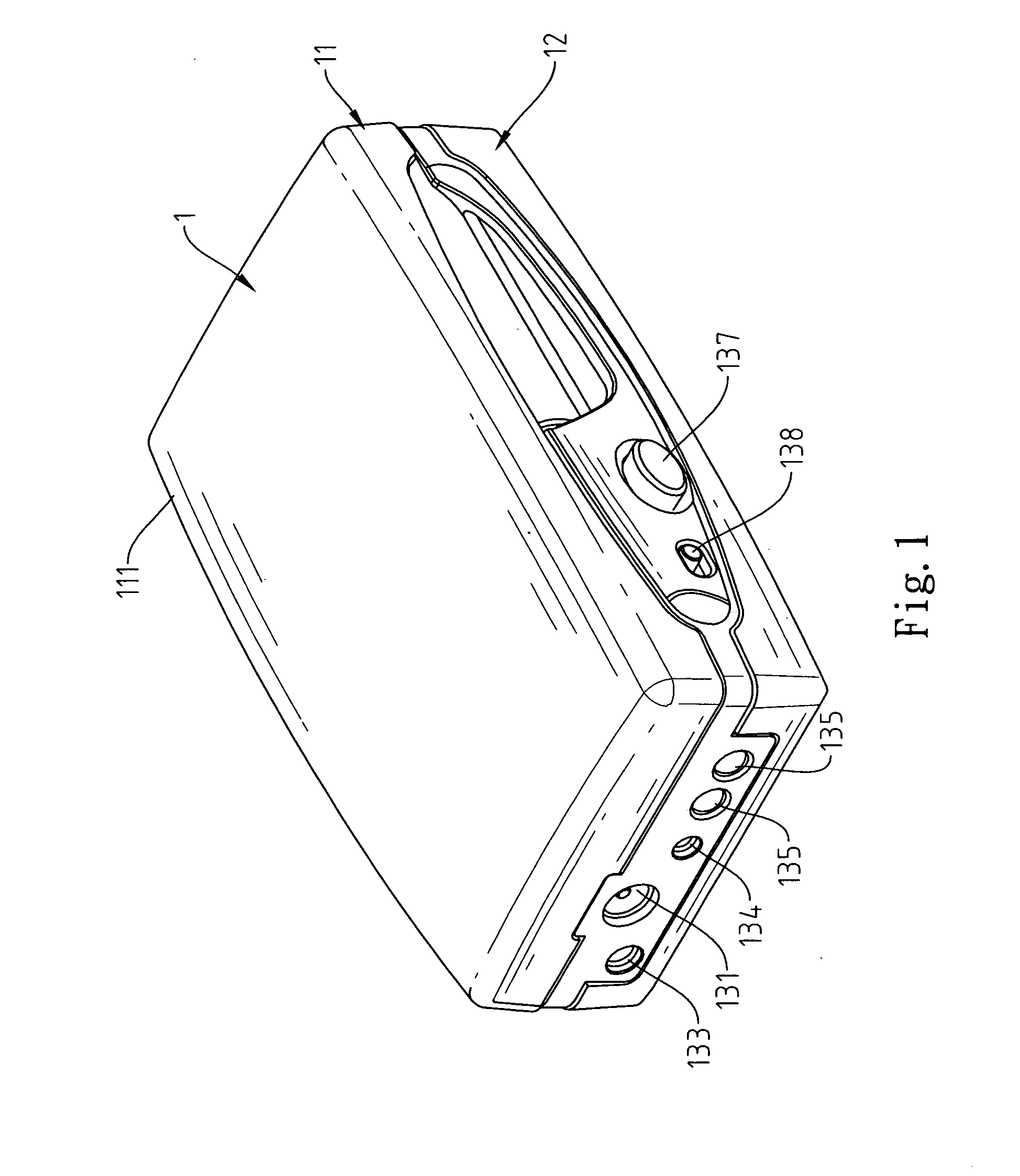
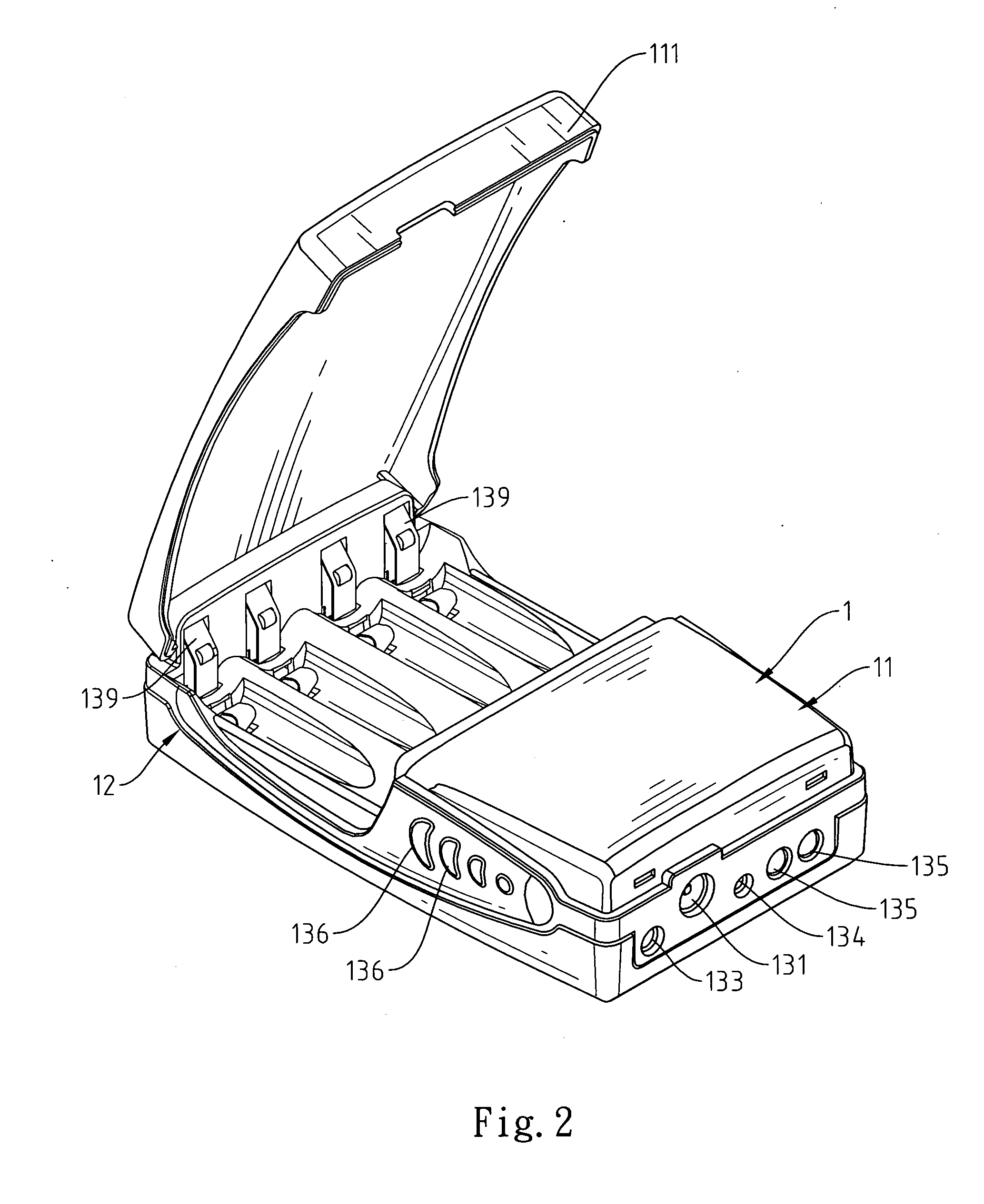
[0016]The charger base 1 comprises a shell 11, a bracket 12, and a circuit control device 13. One lateral surface of the shell 11 is covered with a liftable cover 111. The other lateral surface of the shell 11 is attached to the bracket 12. The circuit control device 13 is mounted between the bracket 12 and the shell 11. The circuit control device 13 comprises a power input socket 131, a USB power input socket 132, a first power output socket 133, a second power output socket 134, several light so...


PUM


Abstract

A portable charging device capable of outputting voltage comprises a charger base, a power supply and a solar panel. The power supply and the solar panel are insertable into the charger base for inputting voltage to the charger base. The charger base is designed for charging rechargeable batteries and supplying various voltages for built-in or external electronic products.

Description

FIELD OF THE INVENTION[0001]The present invention relates to a portable charging device capable of outputting voltage, and more particularly to a portable charging device that charges rechargeable batteries through a power supply and a solar panel and that has power output sockets for supplying electric power for external electronic products so as to provide multiple supplementary functions, reduce energy consumption, and protect environment against secondary pollution.BACKGROUND OF THE INVENTION[0002]The commercial electric power, which acts as a charging source, is usually applied to a general charger. The commercial electric power is a steady power source. However, different countries have different voltage specifications and the charger cannot be applied for charging at any place. As a result, it is still not convenient enough. There is disclosed a charger for connection with the car power. This kind of charger is more convenient than the charger, which is only adaptable to the ...

Claims


Application Information

Patent Timeline
IPC IPC(8): H02J7/00
CPCH02J7/0042H02J7/355H02J7/0055H02J2207/40H02J7/35
Inventor LU, SHENG-FU
Owner LU SHENG FU
Why Eureka
Try Eureka