Apparatus and method for demodulating a modulated signal

a modulated signal and apparatus technology, applied in the field of apparatus and methods for demodulating modulated signals, can solve the problems that the ddc and the following lpf structure cannot be generally simplified, and achieve the effect of simplifying hardwar

Inactive Publication Date: 2008-03-13
WIPRO LTD
View PDF14 Cites 4 Cited by
  • Summary
  • Abstract
  • Description
  • Claims
  • Application Information

AI Technical Summary

Benefits of technology

[0008]An object of the present invention is to provide an apparatus and method for simplifying the hardware of a digital down converter and a low pass filter of the apparatus.

Problems solved by technology

A problem with the hardware typically used in the conventional bandpass sampling techniques is that the DDC and the following LPF structure cannot generally be simplified.

Method used


Image

  • Apparatus and method for demodulating a modulated signal
  • Apparatus and method for demodulating a modulated signal
  • Apparatus and method for demodulating a modulated signal

Examples


Embodiment Construction

[0022]The preferred embodiment of the present invention will be described in detail by way of following examples and with reference to the above-mentioned figures.

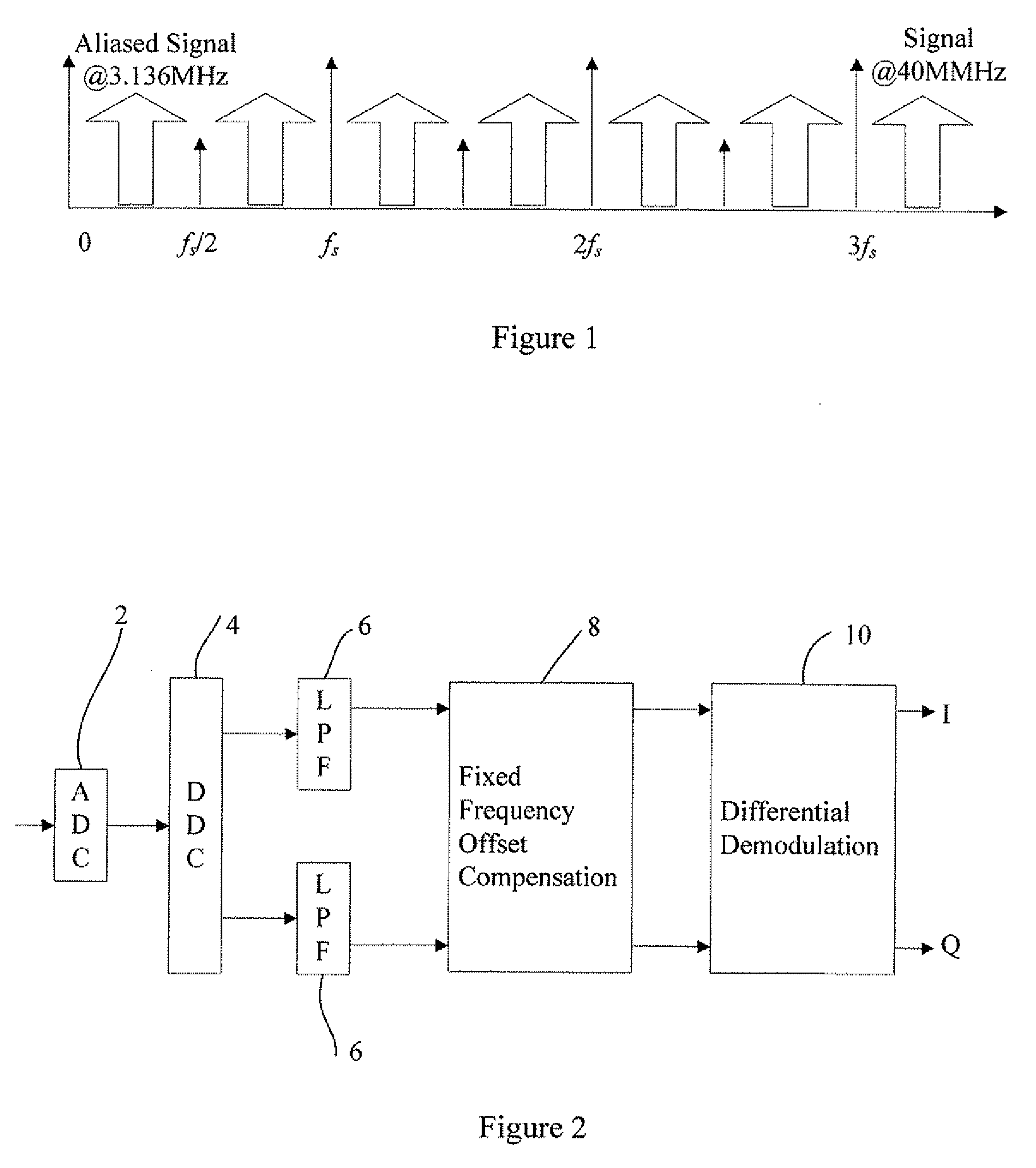
[0023]FIG. 1 is a graph showing the variation of amplitude with frequency for a conventional bandpass sampling apparatus. The spectrum after analog to digital converter is shown for a sampling rate of 12.288 MHz. The amplitude of a positive component is shown at 3.136 MHz, 15.424 MHz, 27.712 MHz and 40 MHz. The amplitude of a negative component is shown at 9.152 MHz, 21.0440 MHz and 33.728 MHz.

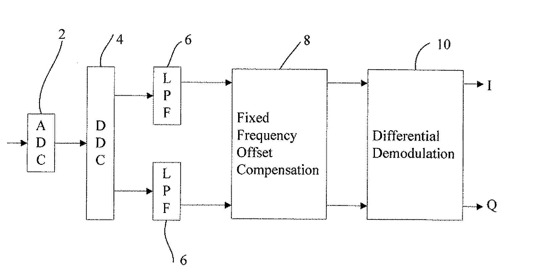
[0024]FIG. 2 shows a block diagram of a number of stages in D-IF receiver of a first preferred embodiment of the invention. The stages shown comprise an analog-to-digital converter 2, a digital down converter 4, two low pass filter stages 6, and a frequency offset compensation stage 8 and a differential demodulator stage 10. An analog modulated input signal is applied to the analog to digital converter 2 where it is sampled at a samp...


PUM


Abstract

An apparatus for demodulating a modulated signal comprises an analog to digital converter (2, 12) for converting an analog modulated input signal to a digital signal. The analog to digital converter is arranged to sample the input signal at a predetermined sampling rate. A digital down converter (4, 14) then receives the digital signal at the sampling rate. The digital down converter has an associated digital intermediate frequency and reduces the frequency of the digital signal to one quarter of the sampling rate. A low pass filter (6, 16) filters selected frequencies from the digital signal. A frequency offset stage (8, 18) applies a modification to the frequency of the filtered signal to reduce frequency offset therein, and a differential demodulator (10, 20) demodulates the signal after modifying the frequency to reduce the frequency offset. There is also disclosed a method for demodulating a signal.

Description

BACKGROUND OF TH INVENTION[0001]1. Field of the Invention[0002]The present invention relates to an apparatus and method for demodulating a modulated signal.[0003]2. Description of Related Art[0004]Bandpass sampling techniques are popular in the field of digital intermediate frequency (D-IF) receivers. In such techniques, a main consideration is to reduce the power consumption by using a lower sampling rate. With bandpass sampling, the sampling rate can be lower than the IF frequency as long as it is higher than two times the bandwidth of a signal being processed.[0005]Conventional bandpass sampling techniques typically oversample the signal being processed whilst undersampling the IF signal. The sampling rate of bandpass sampling should meet the following requirement:2fUn≤fS≤2fLn-11≥n≤⌊fUB⌋(1)Where fU is the highest frequency of the IF signal, fL is the lowest frequency of the IF signal, fS is the sampling rate, and B is the occupied bandwidth of the IF signal. The equivalent digita...

Claims


Application Information

Patent Timeline
Patent Type & Authority Applications(United States)
IPC IPC(8): H03M1/12
CPCH04L27/2075H04L27/0014
Inventor CHANGQING, XUZHIPING, LISAIGUI, HUREN, TAN KAITINGWU, WANGMASAYUKI, TOMISAWA
Owner WIPRO LTD
Why Eureka
Try Eureka