Antenna, method of manufacturing an antenna and apparatus for manufacturing an antenna

a manufacturing method and antenna technology, applied in the field of antennas, can solve the problems of unobtrusive appearance of the antenna, and the appearance of the antenna may be visually unobtrusive, and achieve the effect of cost-effective manufacturing of such an antenna and less obtrusive visual appearan

Inactive Publication Date: 2008-03-13
FRENI ANGELO +3
View PDF2 Cites 9 Cited by
  • Summary
  • Abstract
  • Description
  • Claims
  • Application Information

AI Technical Summary

Benefits of technology

[0006] It is, therefore, an object of the present invention to provide an antenna which can be used in a satellite receiver system and which has a less obtrusive visual appearance than the a

Problems solved by technology

Thus, the antenna may be mounted in a visually unobtrusive manner.
Thus, the plurality of re-radiating elements is arranged in o

Method used


Image

  • Antenna, method of manufacturing an antenna and apparatus for manufacturing an antenna
  • Antenna, method of manufacturing an antenna and apparatus for manufacturing an antenna
  • Antenna, method of manufacturing an antenna and apparatus for manufacturing an antenna

Examples


Embodiment Construction

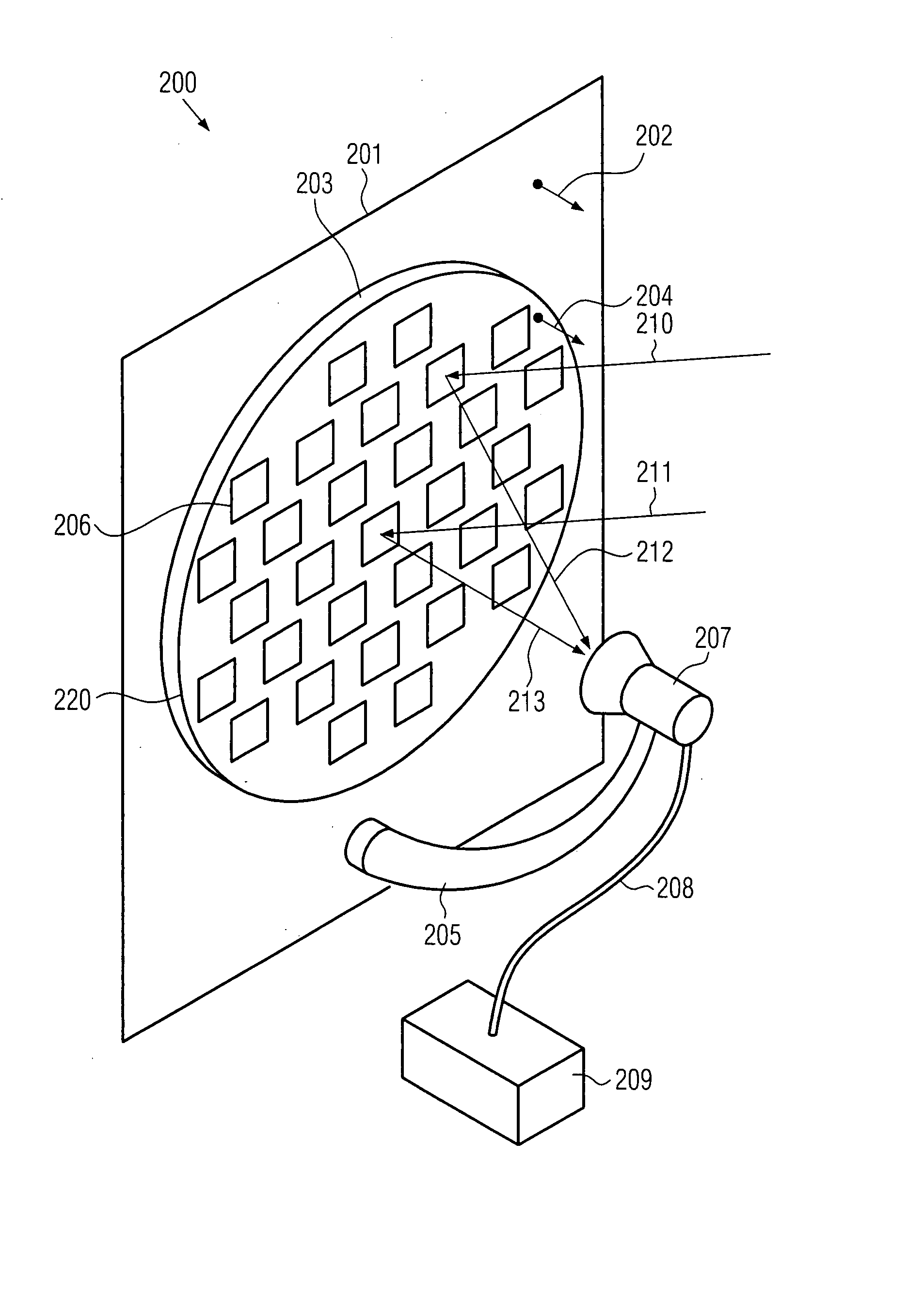
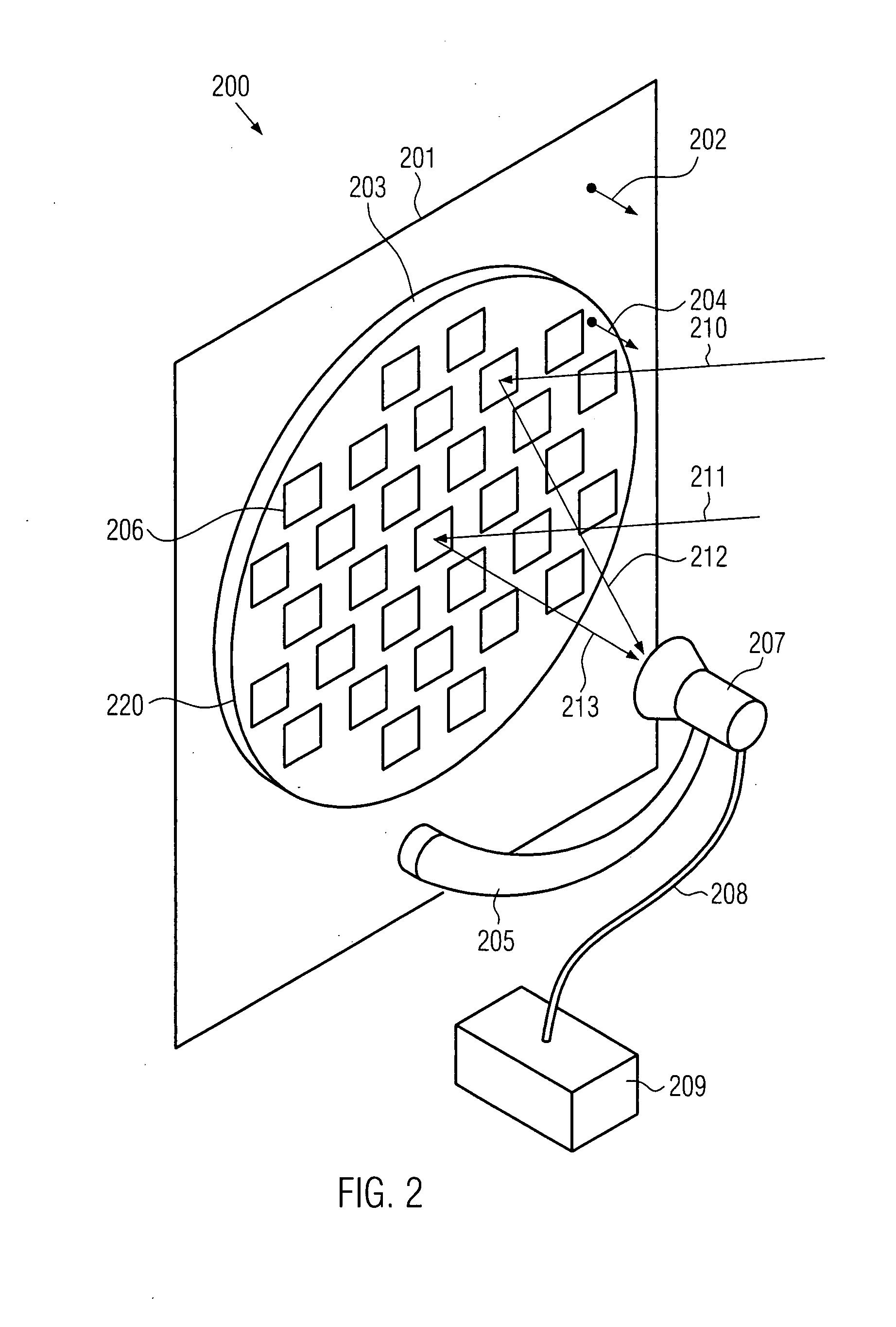
[0058]FIG. 2 shows a schematic perspective view of an antenna 200 according to the present invention.

[0059] The antenna 200 comprises a substrate 203 having a surface 220. The substrate 203 is mounted on a fixed surface 201. A normal direction 204 of the surface 220 of the substrate 203 is substantially parallel to a normal direction 202 of the fixed surface 201. Thus, the fixed surface 201 and the surface 220 of the substrate are substantially parallel to each other.

[0060] The fixed surface 201 can comprise a part of a building. In particular, the fixed surface can comprise a part of a roof, a wall and / or a window of the building.

[0061]FIG. 4a shows a schematic side view of an embodiment of the present invention wherein the antenna 200 is mounted on a roof 402 of a house 403. In this embodiment, the fixed surface 201 is provided in form of a surface of the roof 402. The normal direction 204 of the surface 220 of the substrate 203 can be substantially parallel to the normal direc...


PUM


Abstract

An antenna comprising a plurality of re-radiating elements arranged in at least one plane being parallel to a fixed surface. The arrangement is adapted such that electromagnetic radiation emitted from the re-radiating elements in response to electromagnetic radiation arriving from a predetermined direction interferes constructively at a feed location. Additionally, the antenna comprises a feed provided at the feed location. In a method of manufacturing an antenna, the arrangement of the plurality of re-radiating elements may be calculated and the re-radiating elements can be provided in the at least one plane substantially parallel to the substrate. An apparatus for manufacturing an antenna may comprise a data processor adapted to calculate the arrangement of the plurality of re-radiating elements and means for forming the plurality of re-radiating elements.

Description

FIELD OF THE INVENTION [0001] The present invention relates generally to antennas, and more specifically to antennas comprising a plurality of re-radiating elements, methods of manufacturing antennas comprising a plurality of re-radiating elements and apparatus for manufacturing antennas comprising a plurality of re-radiating elements. BACKGROUND OF THE INVENTION [0002] At present, satellite receiver systems are widely used. In particular, systems for receiving TV signals broadcasted by satellites have become popular in recent years. Satellite receiver systems according to the state of the art comprise an antenna which is connected to receiver electronics. The receiver electronics in turn are connected to a TV. [0003] An antenna for use in a satellite receiver system according to the state of the art will be described with reference to FIG. 1. FIG. 1 shows a schematic perspective view of an antenna 100 according to the state of the art. The antenna 100 comprises a parabolic reflecto...

Claims


Application Information

Patent Timeline
IPC IPC(8): H01Q19/12
CPCH01Q1/1221H01Q1/44H01Q15/142H01Q15/0046H01Q21/0018H01Q15/002H01Q15/0026H01Q19/13H01Q1/24H01Q1/38
Inventor FRENI, ANGELOPIRINOLI, PAOLAZICH, RICCARDODE VITA, PAOLO
Owner FRENI ANGELO
Why Eureka
Try Eureka