
Network Telephony Interface Systems Between Data Network Telephony and Plain Old Telephone Service

a technology of network telephony and interface system, applied in the field of telephone communication, can solve the problems of reducing the cost of service life, affecting the quality of service life, and affecting the quality of service life, and still requiring significant cost and maintenan

Inactive Publication Date: 2008-03-13
GENESYS TELECOMM LAB INC AS GRANTOR +3
View PDF9 Cites 19 Cited by
  • Summary
  • Abstract
  • Description
  • Claims
  • Application Information

AI Technical Summary

Benefits of technology

"The present invention provides a computerized telephony bridge unit that can connect different telephony networks, such as COST and DNT networks. The bridge unit has a trunk-line port for COST calls and a data network port for DNT calls, and can dynamically convert data between the two types of calls. The bridge unit can also retrieve specific data from an incoming call and use it to access a lookup table to determine the associated COST or DNT telephone number, and then use that number to place a call. The invention allows for a seamless and general interface between incompatible telephony networks, which can save time, money, and resources."

Problems solved by technology

This designation is more strictly applied in the language of the art, however, to analog-only systems, and might be confusing to many if used in the context of this specification.
As a result, real-time voice communication may at times suffer dropout and delay.
This is at least partially due to packet loss experienced during periods of less than needed bandwidth which may prevail under certain conditions such as congestion during peak periods of use, and so on.
However, telephony trunks and IPNT network lines representing the separate networks involved still provide for significant costs and maintenance.
Routing and other equipment, however, must be implemented at both the call-center level and network level significantly reducing any realized cost savings.
A significant disadvantage of such a bridge, having dedicated equipment on each end, is the dedicated nature of individual channels over the bridging link.
Efficient use of bandwidth cannot be assured during variable traffic conditions that may prevail at certain times. For example, dedicated channels assigned to IPNT traffic would not be utilized if there were not enough traffic to facilitate their use.
Therefore, additional requirements for equipment and inefficiency regarding use of bandwidth are still factors.

Method used


Image

  • Network Telephony Interface Systems Between Data Network Telephony and Plain Old Telephone Service
  • Network Telephony Interface Systems Between Data Network Telephony and Plain Old Telephone Service
  • Network Telephony Interface Systems Between Data Network Telephony and Plain Old Telephone Service

Examples


Embodiment Construction

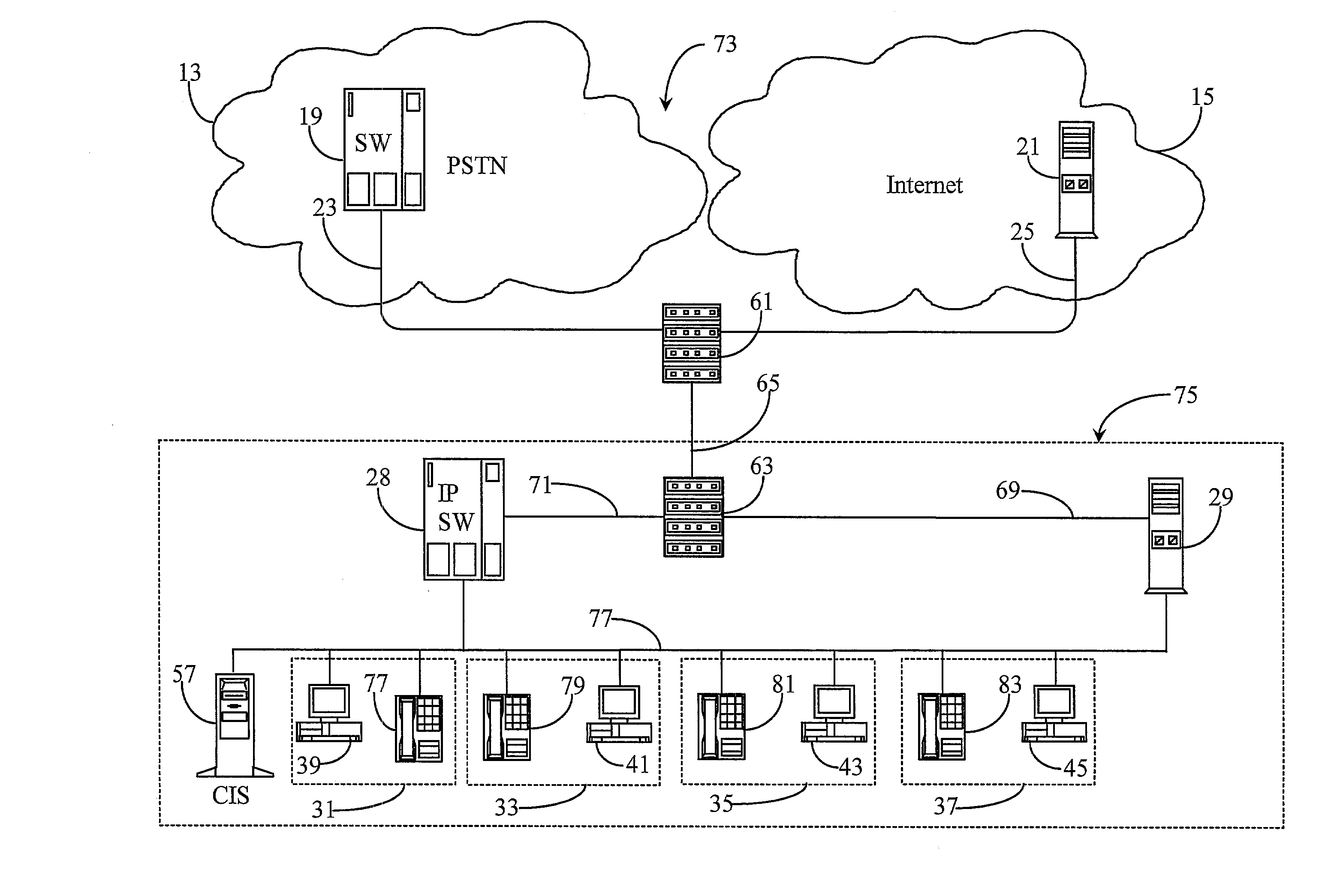
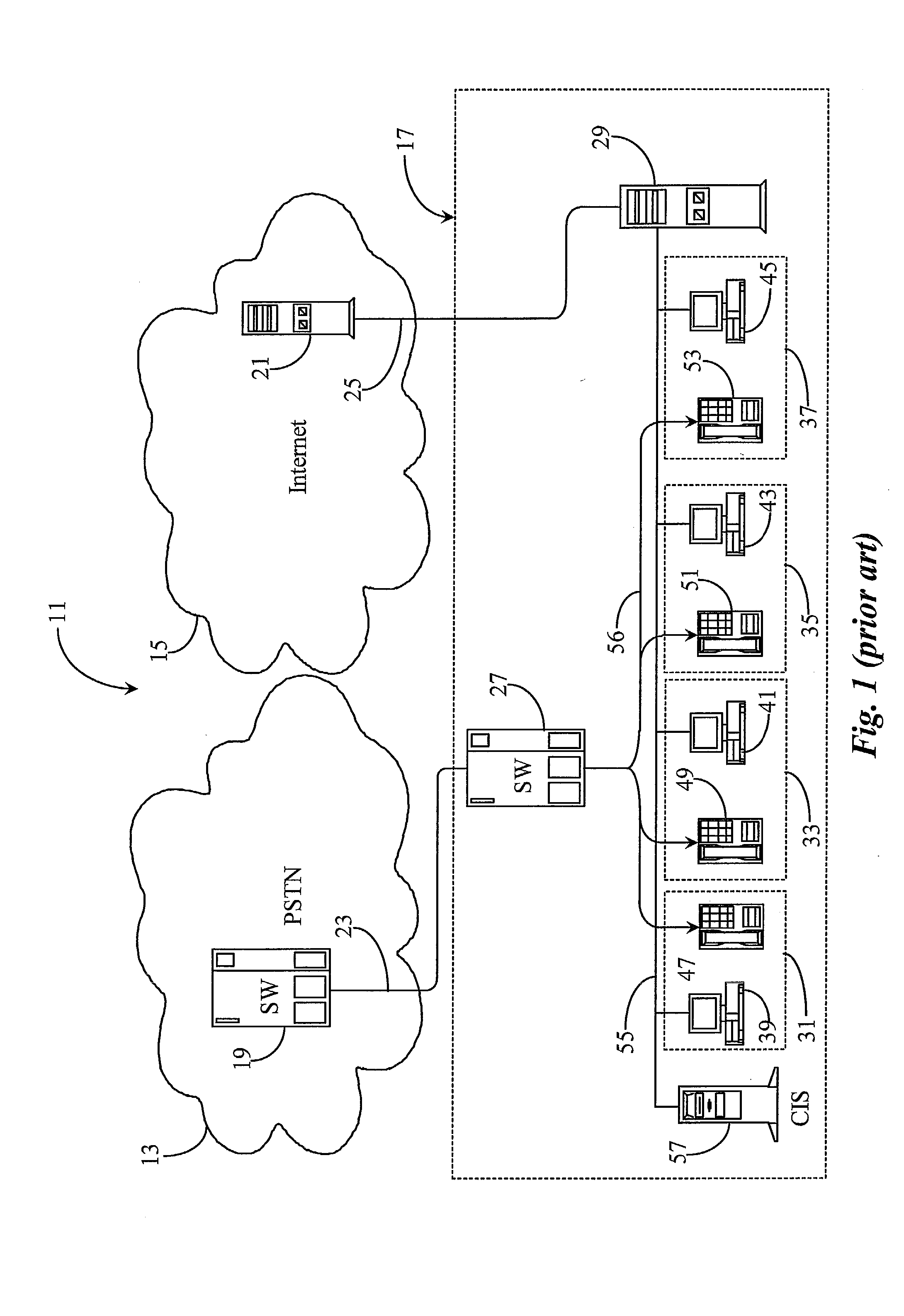
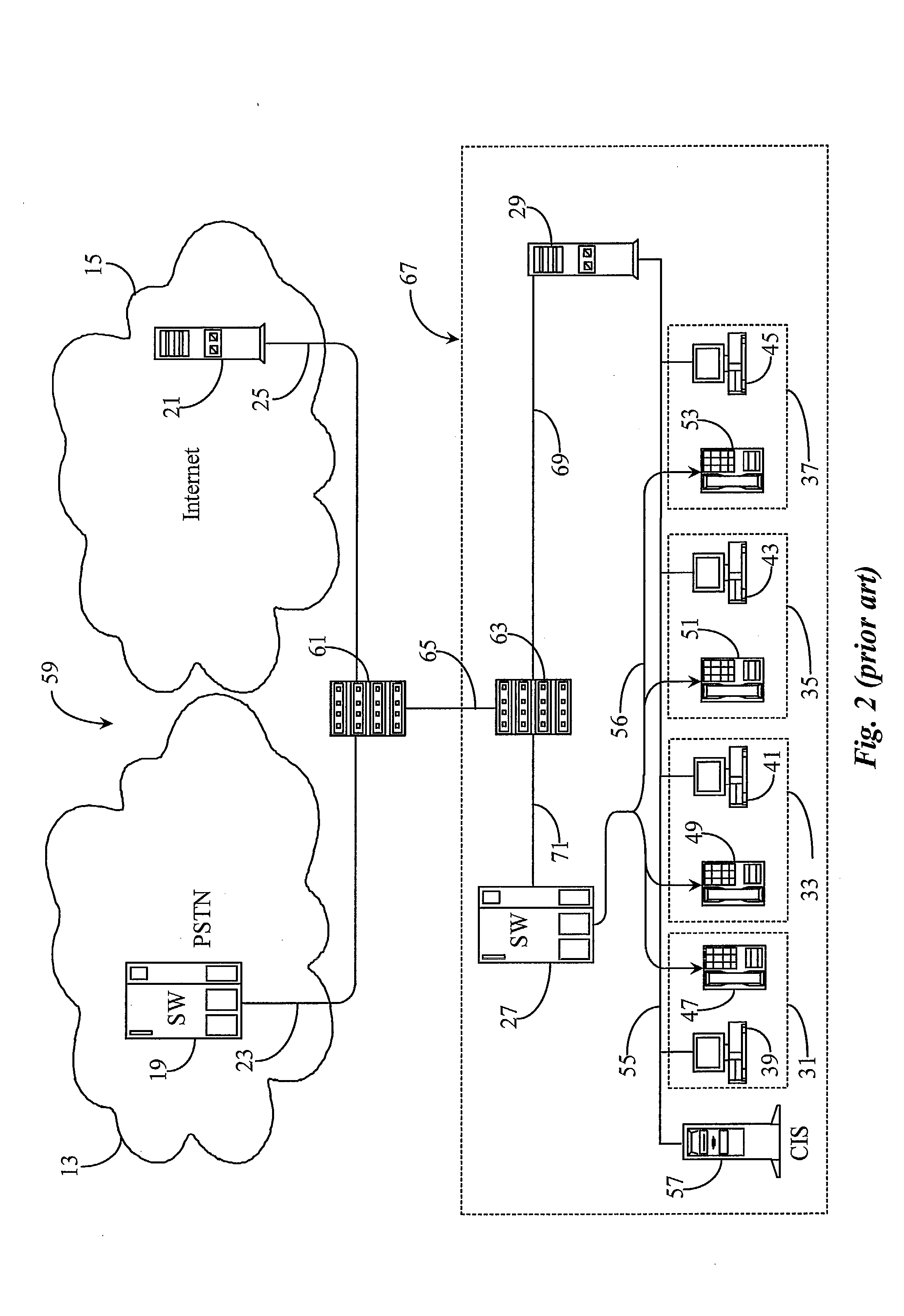
[0029]FIG. 1 is a system diagram of a prior art call center and network connections, wherein the call center is capable of both COST and IPNT call handling. In FIG. 1 telecommunications network 11 comprises a publicly-switched telephone network (PSTN) 13, the Internet network 15, and a call center 17. PSTN network 13 may be a private network rather than a public network, and Internet 15 may be another public or a private data network as are known in the art.

[0030] In this basic prior art example, call center 17 is equipped to handle both COST calls and IPNT calls. Both COST calls and IPNT calls are delivered to call-center 17 by separate network connections. For example, a telephony switch 19 in the PSTN may receive incoming telephone calls and rout them over a COST network connection 23 to a central switching apparatus 27 located within call center 17. IPNT calls via Internet 15 are routed via a data router 21 over a data-network connection 25 to an IPNT router 29 within call cent...


PUM


Abstract

A computerized telephony bridge unit has a Data Network Telephony (DNT) Port and a Connection Oriented / Switched Telephony (COST) trunk port, each associated with circuitry for receiving a placing calls in the data format required by connected networks. The bridge unit further comprises conversion circuitry for converting data dynamically between network protocols compatible with each connected network. Control routines executable on the computerized bridge unit are adapted to receive a first call from one of the COST and DNT networks, to place a call associated with the received call on the network other than the network on which the call is received, and to dynamically convert data between a call connected at one port and a call connected at the other port. The data network can be the Internet, and the COST network can be any publicly or privately switched dedicated-connection-oriented telephone network. Association between calls between two otherwise incompatible networks can be by a locally-stored lookup table, by negotiation with a caller, or by retrieval of data from incoming calls. Methods for practicing the invention are taught in the disclosure.

Description

FIELD OF THE INVENTION [0001] The present invention is in the field of telephony communication and pertains more particularly to methods and apparatus for seamless interfacing and integration of telephony on different networks. BACKGROUND OF THE INVENTION [0002] In the field of telephony communication, there have been many in technology over the years that have contributed to more efficient use of telephone communication within hosted call-center environments. Most of these improvements involve integrating the telephones and switching systems in such call centers with computer hardware and software adapted for, among other things, better routing of telephone calls, faster delivery of telephone calls and associated information, and improved service with regards to client satisfaction. Such computer-enhanced telephony is known in the art as computer-telephony integration (CTI). [0003] Generally speaking, CTI implementations of various design and purpose are implemented both within ind...

Claims


Application Information

Patent Timeline
Patent Type & Authority Applications(United States)
IPC IPC(8): H04L12/66H04M3/42H04L29/06H04M3/00H04M3/51H04M7/00H04M11/00H04Q3/64
CPCH04L29/06H04L65/103H04M3/42323H04M3/51H04M7/006H04Q3/64H04Q2213/13034H04Q2213/1307H04Q2213/13097H04Q2213/13196H04Q2213/13204H04Q2213/1322H04Q2213/13389H04L65/104H04L29/06027H04L65/1101H04L9/40
Inventor KIKINIS, DAN
Owner GENESYS TELECOMM LAB INC AS GRANTOR
Learn More