Subsea connector insulation device

a technology of connectors and insulation devices, which is applied in the direction of insulation, special purpose vessels, and borehole/well accessories, etc., can solve the problems of affecting the sealing effect of the subsea connector, so as to reduce reduce the effect of reducing the convective heat loss, and reduce the effect of convective heat loss

Active Publication Date: 2008-03-13
DEEP SEA TECH
View PDF40 Cites 32 Cited by
  • Summary
  • Abstract
  • Description
  • Claims
  • Application Information

AI Technical Summary

Benefits of technology

[0018] In certain embodiments, the fluid used to inflate the bag is an incompressible and/or insulating fluid. The inflated bag may thermally insulate the subsea component from the surrounding environment. The bag may at least partially conform to the surface of the subsea component when inflated. The bag may substantially seal against the surface of the subsea component to inhibit fluid from circulating between the bag and the su

Problems solved by technology

As fluids flow from the subsea development to the gathering platform, the temperature of the fluids decreases, sometimes significantly, as heat is lost to the surrounding seawater.
The connectors on the ends of the jumpers, however, cannot be insulated prior to subsea installation.
These features inhibit placing insulation on the connectors prior to installation.
Without insulation, significant heat losses would take place from the connectors.
The “dog house” configuration is inefficient in providing insulation against heat loss to seawater.
The molded insulation in the “dog house” configuration typically does not achieve proper (e.g.,

Method used


Image

  • Subsea connector insulation device
  • Subsea connector insulation device
  • Subsea connector insulation device

Examples


Embodiment Construction

[0034] In the context of this patent, the term “bag” means a container that can be conformed and is configured to at least partially contain, or enclose, one or more objects and / or materials. The bag may be inflatable. The bag may be inflated using a fluid (e.g., a gas, a liquid, a gel, and / or a slurry).

[0035] In the context of this patent, the term “coupled” means either a direct connection or an indirect connection (e.g., one or more intervening connections) between one or more objects or components. The phrase “directly connected” means a direct connection between objects or components such that the objects or components are connected directly to each other so that the objects or components operate in a “point of use” manner.

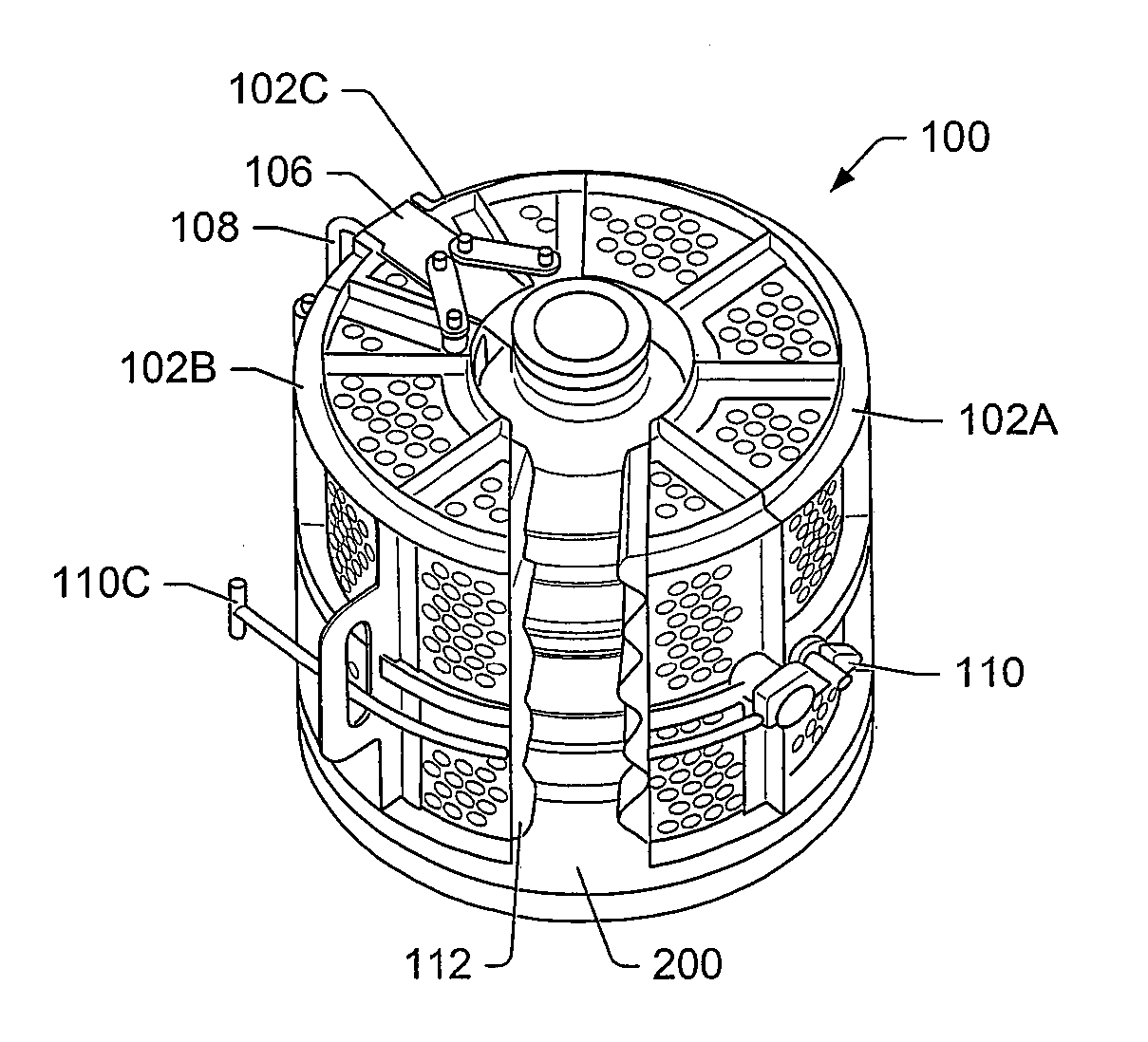
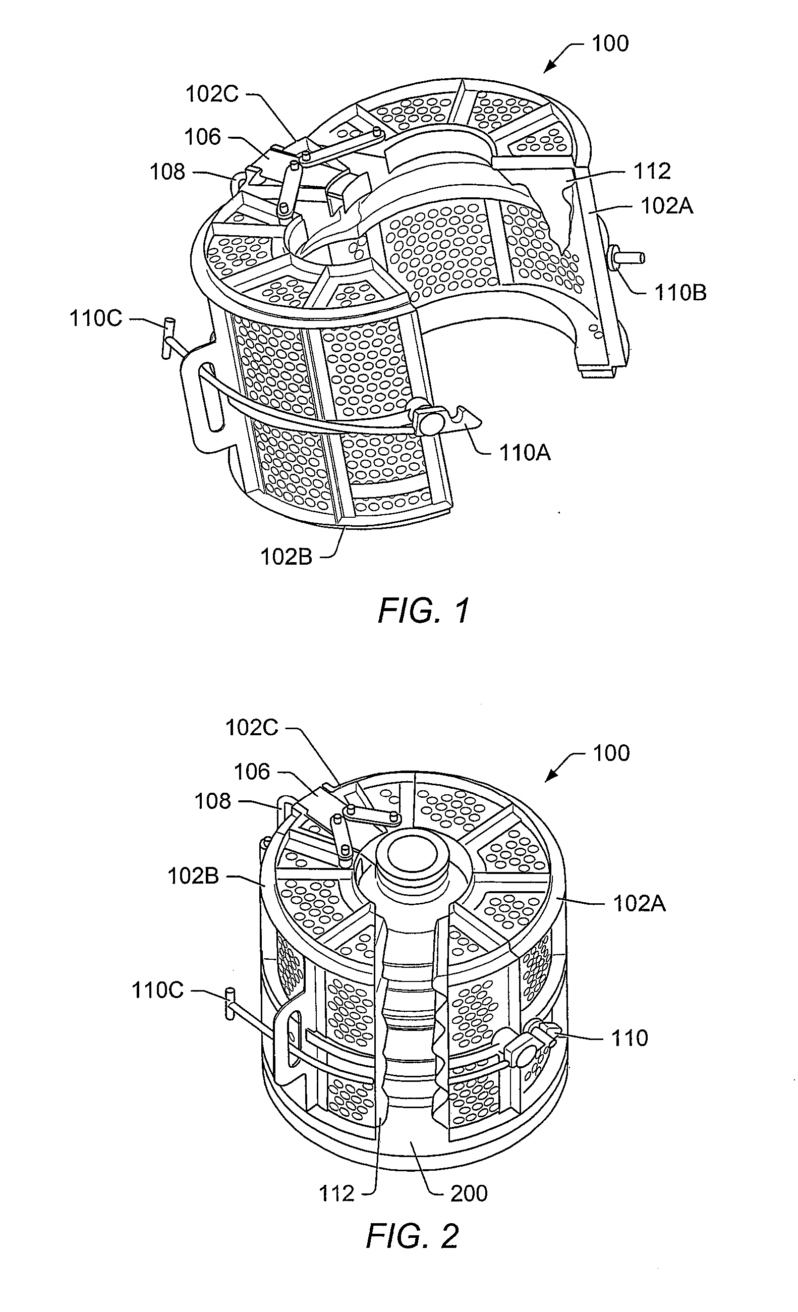
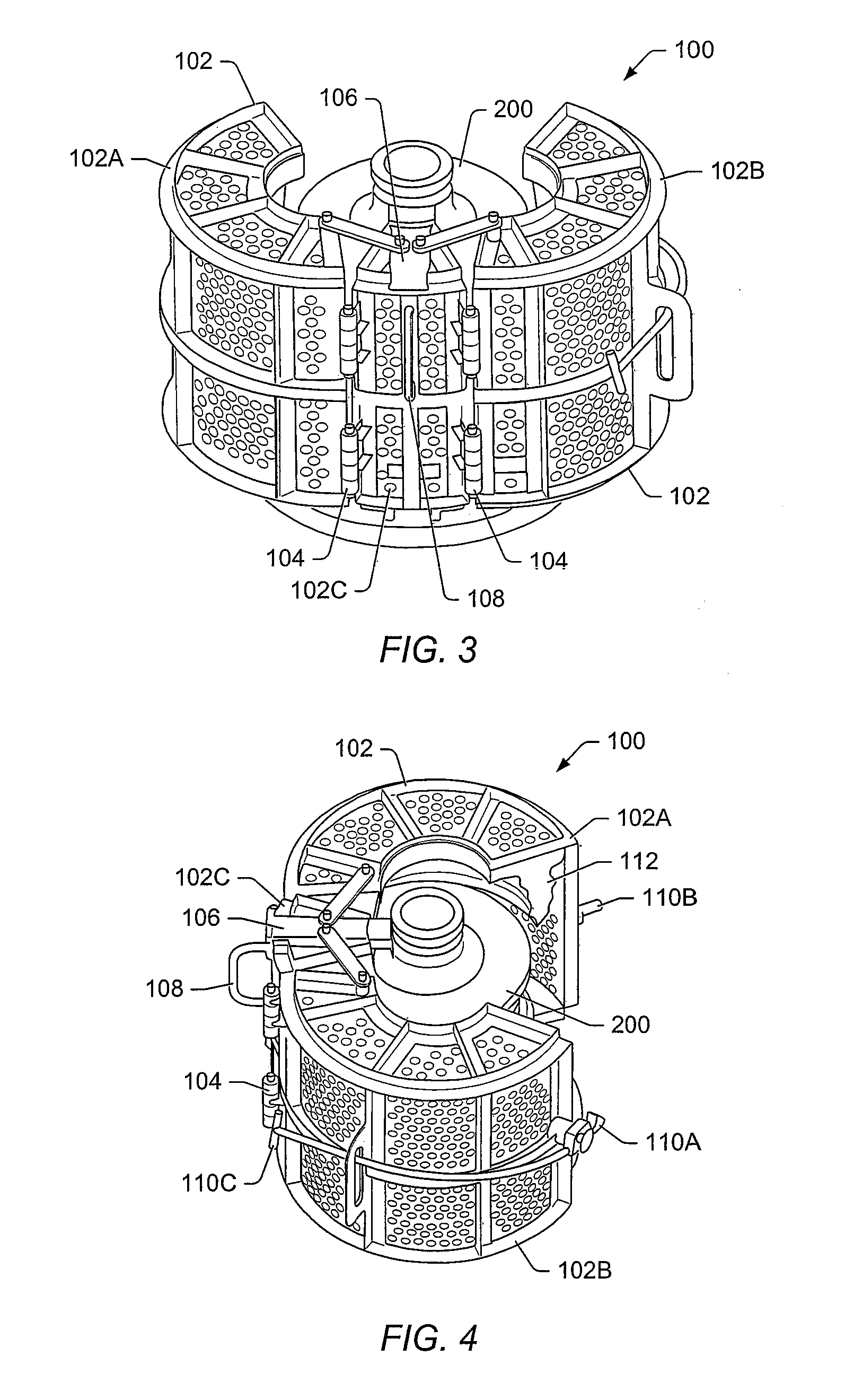
[0036]FIG. 1 depicts a representation of an embodiment of subsea connector insulation device 100 in an open configuration. FIG. 2 depicts a representation of an embodiment of device 100 in a closed configuration around subsea connector 200 with a portion of...


PUM


Abstract

A subsea insulation device is described. The device includes a frame coupled to and at least partially enclosing a subsea component. A bag may be at least partially enclosed in the frame. The bag may substantially seal against at least one surface of the subsea component when the bag is at least partially inflated. A port may be attached to the bag. The port may allow the bag to be coupled to a fluid provider connector so that fluid can be provided into the bag to inflate the bag.

Description

PRIORITY CLAIM [0001] This patent application claims priority to U.S. Provisional Patent No. 60 / 796,443 entitled “SUBSEA CONNECTOR INSULATION SHROUD” to Reddy filed on May 1, 2006.BACKGROUND [0002] 1. Field of the Invention [0003] The present invention relates to subsea connectors and devices for insulating the subsea connectors. More particularly, the invention relates subsea connector insulation devices that are installable using remotely operated vehicles (ROVs). [0004] 2. Description of Related Art [0005] Subsea oil and gas field developments typically include one or more subsea wells and / or subsea components located at large depths and distances from a gathering platform (e.g., an oil gathering rig). The gathering platform may be a fixed or a floating platform. Production from the subsea wells is routed to the gathering platform through flowlines and / or subsea manifolds. [0006] A field development may be a multi-well subsea development. The multi-well subsea development may inc...

Claims


Application Information

Patent Timeline
IPC IPC(8): F16L57/00
CPCE21B36/003F16L59/18E21B41/0007Y10T137/7036
Inventor REDDY, SANJAY KONDA
Owner DEEP SEA TECH
Why Eureka
Try Eureka