
Pipeline flexible connecting device and using method thereof

A flexible connection and pipeline technology, applied in the direction of pipe joints, adjustable connections, heating devices, etc., can solve the problems of not being able to control the heat energy loss of the system well, inconvenient production and installation, and affecting the safety of operation, so as to avoid sudden Effects of large-scale leakage, low cost, and low heat loss

Active Publication Date: 2013-08-21
BEIJING TERASOLAR PHOTOTHERMAL TECH CO LTD
View PDF8 Cites 4 Cited by
  • Summary
  • Abstract
  • Description
  • Claims
  • Application Information

AI Technical Summary

Problems solved by technology

[0003] At present, in the existing commercialized trough collector system, two parallel collector terminals need to be connected in series through flexible pipelines to complete a heat collecting working medium or the output terminal of a single heat collector transports the heated working medium into the branch pipe. Due to the particularity of the trough tracking, the heat collector changes with the position of the sun, but the relative position of the branch pipe is fixed. Therefore, the two need to be connected to each other through a flexible pipeline connection device. The existing flexible connection is designed as a three-dimensional connection spherical movable joint or a bellows structure. The former has a complex structure, is inconvenient to produce and install, and is expensive. The possibility of leakage cannot be avoided; the latter is connected by bellows. Although the structure is simple and easy to install, it has the possibility of sudden leakage. rupture, a sudden large-scale leakage occurs, which seriously affects the safety of operation; at the same time, it is difficult for the two to achieve good heat preservation during the work process, and it is impossible to control the heat loss of the system well

Method used


Image

  • Pipeline flexible connecting device and using method thereof
  • Pipeline flexible connecting device and using method thereof
  • Pipeline flexible connecting device and using method thereof

Examples


Embodiment Construction

[0027] Specific embodiments of the present invention will be described in detail below with reference to the accompanying drawings.

[0028]

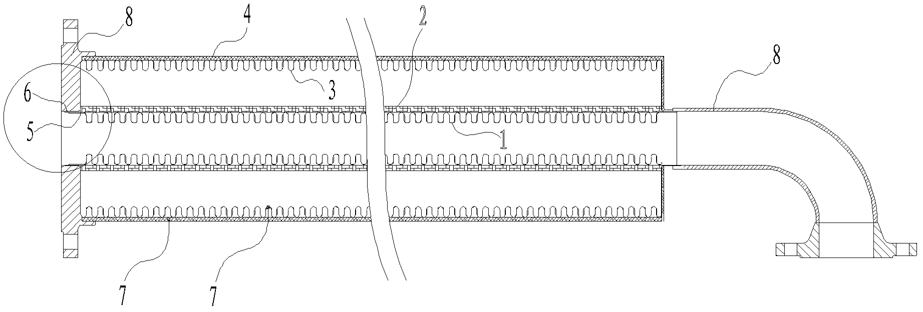
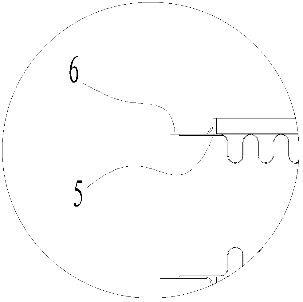
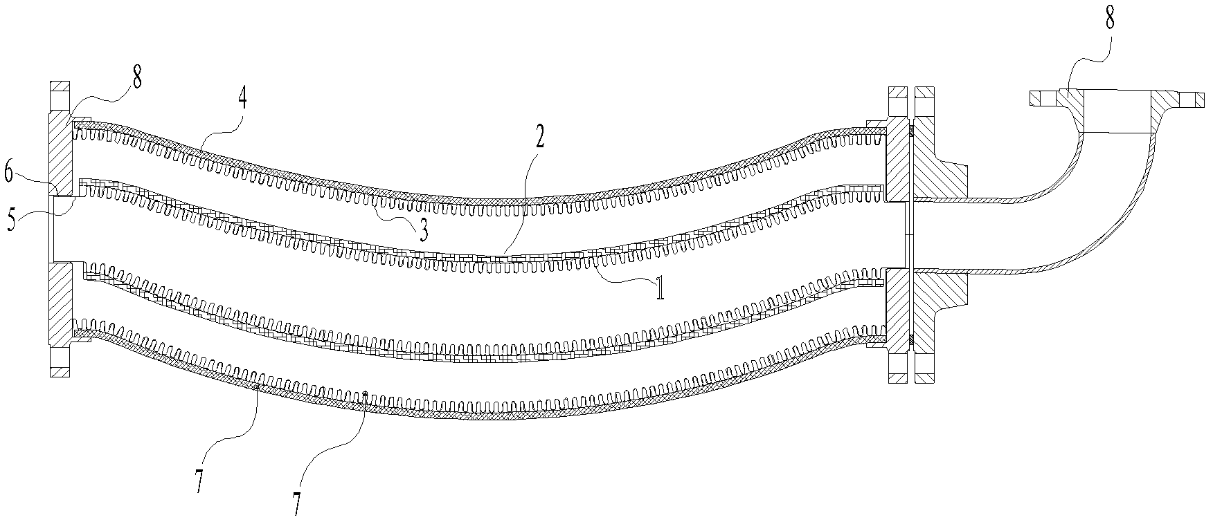
[0029] figure 1 It is a structural schematic diagram of the first implementation of the pipeline flexible connection device of the present invention; the pipeline flexible connection device is composed of at least one group of pipeline flexible connection device units, and each group of device units is composed of no less than two layers of metal bellows and two At least one closed space is formed between the metal bellows that are nested in each other. The metal bellows includes a bellows structure and a straight metal pipe with a certain length at the end; Among them, at least one layer of metal bellows is provided with a reinforcing layer on the outside.

[0030] Such as figure 1 As shown, a single device unit of the pipeline flexible connection device specifically includes a first metal bellows 1, a first reinforcement layer 2 ar...


PUM


Abstract

The invention provides a pipeline flexible connecting device which is composed of at least one set of pipeline flexible connecting device unit. Each set of device unit is formed by no less than two layers of mutually-sleeved metal corrugated pipes and connecting members at two ends, and the pipeline flexible connecting device is characterized in that at least one closed space is formed among the mutually-sleeved metal corrugated pipes, at least one temperature is arranged on walls of a metal corrugated layer or a reinforcing layer of the pipeline flexible connecting device to monitor temperature during operating, and leakage alarming of the pipeline flexible connecting device is realized by judging obtained temperature change information. The pipeline flexible connecting device is safe in operating, low in cost, long in service life, high in strength, small in heat waste and good in flexible controllability and monitoring controllability.

Description

technical field [0001] The invention relates to a pipeline flexible connection device, in particular to a pipeline flexible connection device in the field of solar heat utilization. Background technique [0002] Hose is an important connecting component in engineering technology, which is composed of flexible pipes and joints. Used as compensating elements, sealing elements, connecting elements and shock absorbing elements in various gas transmission, infusion pipeline systems and length, temperature, position and angle compensation systems, used in aerospace, petrochemical, mining electronics, machinery shipbuilding, medical treatment Health, textile electronics, energy construction and other fields. [0003] At present, in the existing commercialized trough collector system, two parallel collector terminals need to be connected in series through flexible pipelines to complete a heat collecting working medium or the output terminal of a single heat collector transports th...

Claims


Application Information

Patent Timeline
Patent Type & Authority Applications(China)
IPC IPC(8): F16L27/10F16L39/04F16L59/065F24J2/46
CPCF16L11/15F16L11/22F16L59/065F16L2201/30
Inventor 刘阳
Owner BEIJING TERASOLAR PHOTOTHERMAL TECH CO LTD
Learn More