Device and technique using rotary kiln barrel heat to generate power

A technology of rotary kiln and thermal power generation, applied in the field of waste heat utilization of cement kilns, can solve the problems of low waste heat utilization efficiency, small power generation, affecting boiler efficiency, etc., to improve convenience, improve heat exchange efficiency, and improve radiation heat exchange absorption. rate effect

Inactive Publication Date: 2015-12-09
CITIC HEAVY INDUSTRIES CO LTD
View PDF9 Cites 2 Cited by
  • Summary
  • Abstract
  • Description
  • Claims
  • Application Information

AI Technical Summary

Problems solved by technology

[0003] The purpose of the present invention is to solve the problem of efficient utilization of cement rotary kiln shell heat, specifically to solve the problems of low waste heat utilization efficiency and large production fluctuations affected by seasons in the traditional way of using the heat of the rotary kiln shell to generate hot water. And solve the problems of the thermal heating of the rotary kiln shell and the utilization of condensate water for power generation, which affect the boiler efficiency and the small power generation, and finally realize the high-efficiency utilization of the rotary kiln shell heat

Method used


Image

  • Device and technique using rotary kiln barrel heat to generate power
  • Device and technique using rotary kiln barrel heat to generate power
  • Device and technique using rotary kiln barrel heat to generate power

Examples


Embodiment Construction

[0027] The present invention will be further described in detail below in conjunction with the accompanying drawings and specific embodiments.

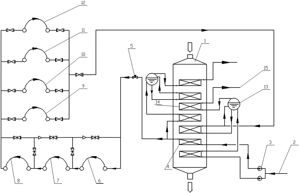
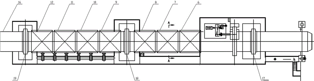
[0028] According to the accompanying drawings, a device for generating electricity by using the heat of the rotary kiln shell, including: the rotary kiln shell, 1# wheel belt 17, 2# wheel belt 18, 3# wheel belt 19 and kiln head dual-pressure waste heat boiler 1 , the feedwater end of the kiln head double-pressure waste heat boiler 1 is provided with a deaerator 2 and a medium-pressure feedwater pump 3, and the surface of the rotary kiln cylinder between the 1# wheel belt 17 and the 2# wheel belt 18 is sequentially There are heat exchange surface I6, heat exchange surface II7 and heat exchange surface III8, and the surface of the rotary kiln cylinder between the 2# wheel belt 18 and the 3# wheel belt 19 is provided with heat exchange surface IV9, heat exchange surface V10, heat exchange surface VI11 and heat exchange surface VII12, the...


PUM


Abstract

The invention relates to a device and technique using rotary kiln barrel heat to generate power. The device comprises a rotary kiln barrel, a first wheel belt, a second wheel belt, a third wheel belt and a kiln-head dual-pressure waste heat boiler. A deaerator and a medium-pressure water feeding pump are arranged at the water feeding end of the kiln-head dual-pressure waste heat boiler; a first heat exchanging face, a second heat exchanging face and a third heat exchanging face are sequentially arranged at the position, between the first wheel belt and the second wheel belt, on the surface of the rotary kiln barrel; a fourth heat exchanging face, a fifth heat exchanging face, a sixth heat exchanging face and a seventh heat exchanging face are sequentially arranged at the position, between the second wheel belt and the third wheel belt, on the surface of the rotary kiln barrel; and the heat exchanging faces are sequentially provided with membrane type water cooling walls, thermal-insulation rock wood and casings from inside to outside. The device solves the problems that a traditional method using rotary kiln barrel heat to generate hot water is low in waste heat utilizing efficiency and large in production fluctuation caused by seasons. Furthermore, the device solves the problems that a method using rotary kiln barrel heat to heat condensation water to generate power affects the boiler efficiency and is small in generating capacity. Finally, the rotary kiln barrel heat can be efficiently utilized.

Description

technical field [0001] The invention relates to the field of cement kiln waste heat utilization, in particular to a device and a process for generating low-pressure steam by absorbing the heat of a cement rotary kiln cylinder and generating electricity. Background technique [0002] The cement industry is a big consumer of energy and a big waste. In the large-scale dry process cement production line, due to the limitation of calcination technology and production process, the low-temperature waste heat below 350 ℃ discharged externally accounts for more than 35% of the total heat consumption of the cement clinker sintering system, of which the rotary kiln barrel at 250-350 ℃ Body surface heat loss accounts for about 5%. The existing cement kiln waste heat power generation technology only uses the waste heat of the flue gas discharged from the cement production line. For the heat dissipation on the surface of the rotary kiln shell, direct heat exchange is generally used to ge...

Claims


Application Information

Patent Timeline
Patent Type & Authority Applications(China)
IPC IPC(8): F27D17/00F22B1/00
CPCY02P10/25
Inventor 彭岩刘怀亮时小宝吴海燕何汪海姚斌李磊
Owner CITIC HEAVY INDUSTRIES CO LTD
Why Eureka
Try Eureka