Differnttal gearing unit with controllable torque and rotational speed distribution

a technology of differential gearing and controllable torque, which is applied in differential gearings, toothed gearings, electric energy vehicles, etc., can solve the problems of unfavorable rotational speed ratio, small amount of power, and considerable overall loss

Inactive Publication Date: 2008-03-13
MAGNA STEYR FAHRZEUGTECHN
View PDF5 Cites 41 Cited by
  • Summary
  • Abstract
  • Description
  • Claims
  • Application Information

AI Technical Summary

Benefits of technology

[0007] It is therefore the object on which the invention is based to provide a generic differential gearing unit which, while being of low weight and having low space and energy requirements, permits precise control with a low-power auxiliary drive. This is provided according to the invention in that the first and second planet gears are arranged on a common planet carrier, and in that, in the superposition gearing, the first sun gear is rotationally fixedly connected to the housing of the differential gearing unit, the second sun gear is driven by the auxiliary drive, and the first ring gear is rotationally fixedly connected to an output shaft.
[0008] A superposition gearing of a design of said type does not call upon the auxiliary drive when the two output shafts are at the same rotational speed. Said auxiliary drive can therefore be at standstill in normal operation and requires no energy. Furthermore, this results in clear kinematic relationships, which benefits precise control. In this way, the differential gearing unit according to the invention can be used in an unrestricted manner both as an axle differential and also as an inter-axle differential (or central differential).
[0009] With a planetary gear set of said type, it is possible to provide a high transmission ratio for the auxiliary drive, and the functionality is independent of the vehicle speed, which results in a relatively simple and very fine control. Above all, however, the highest possible transmission ratio can be obtained when an electric motor is used as an auxiliary drive as a result of the connection thereof to the sun gear of the one planetary gear set, and a low-power high-speed electric motor can thus be used. As a result, the auxiliary drive only absorbs a small amount of power, which also benefits the installation size. An output drive by means of the ring gears results in the lowest absolute and differential rotational speeds and therefore the lowest losses and the least noise generation in the overall system. Since it is the vehicle dynamics which are being controlled, that is to say when traveling at (high) road speed, the control range need not be very wide.
[0010] It is finally the case in said arrangement that the tangential forces to be withstood by the planet gears are very small, so that the two planet sets can be designed to be very small. As a result, the entire differential gearing unit is only an insignificant amount larger than a conventional differential gearing. Furthermore, it is possible in this way to select the number of teeth of the gearwheels of the two planet stages to be in each case identical, which permits—in a cost-reducing manner—an increased number of identical parts.
[0012] One particularly favorable arrangement of the auxiliary drive and the bearing of the concentric shafts is made possible if the second sun gear is seated on a hollow shaft which surrounds the rotationally fixed connection between the first sun gear and the housing, which hollow shaft is drive-connected to the auxiliary drive.
[0013] The auxiliary drive can be of any desired type as long as it permits tractive and braking operation in a controllable fashion in both rotational directions. Said auxiliary drive is preferably a controllable electric motor with a step-down gearing. Its installation, power supply and connection to a control unit accommodated elsewhere are thus particularly simple.

Problems solved by technology

Corresponding to the lower rotational speeds of hydraulic motors, the auxiliary drive engages on one of the ring gears, which results in unfavorable rotational speed ratios and also, on account of the drive output via the planet carrier, considerable overall losses—even when driving in a straight line.
As a result, the auxiliary drive only absorbs a small amount of power, which also benefits the installation size.

Method used


Image

  • Differnttal gearing unit with controllable torque and rotational speed distribution
  • Differnttal gearing unit with controllable torque and rotational speed distribution
  • Differnttal gearing unit with controllable torque and rotational speed distribution

Examples


Embodiment Construction

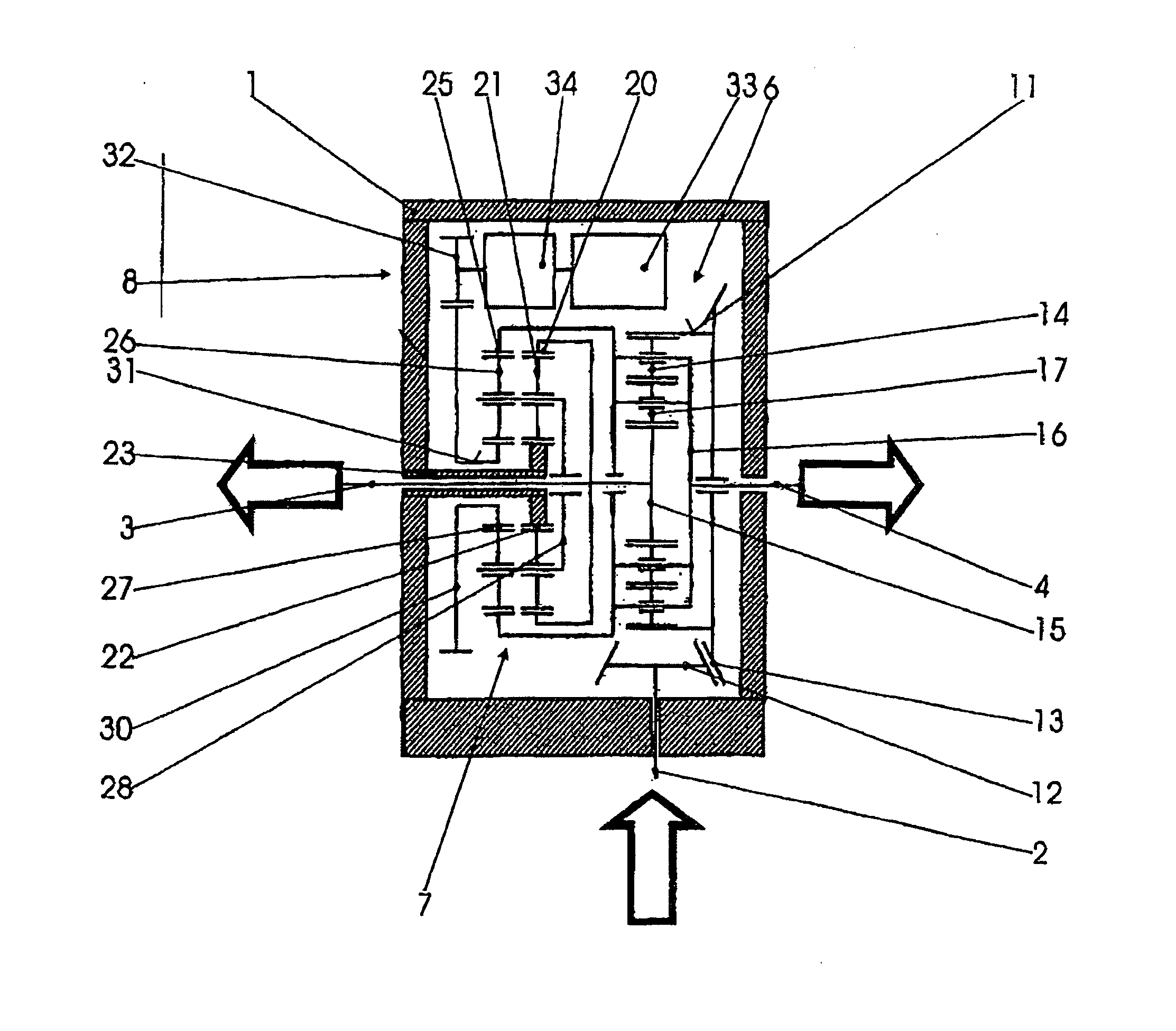
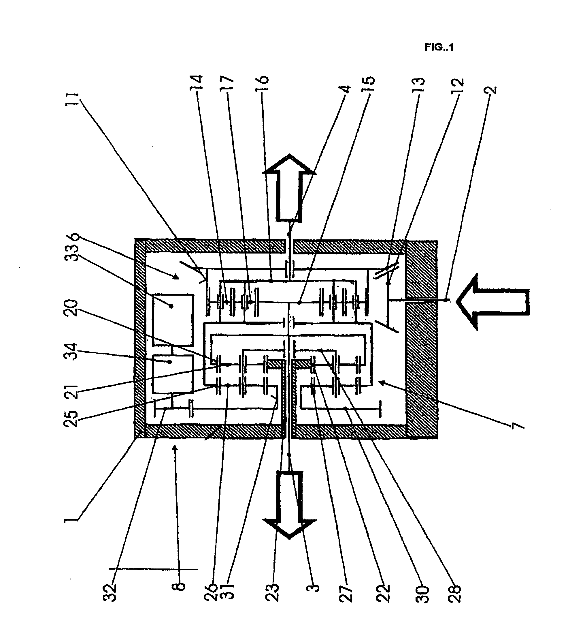
[0017] The entire differential gearing unit is situated in a housing 1 which is fixed to the vehicle. The drive force for the vehicle is provided via a drive input shaft 2 either directly or indirectly from an engine-transmission unit (not illustrated), depending on the arrangement of the drivetrain and on whether the differential gearing unit is an axle differential or an inter-axle differential. A first output shaft 3 and a second output shaft 4 are guided out of the housing 1 at opposite sides. Said output shafts are either axle shafts which lead to the wheels of an axle or shafts which lead to two driven axles. A differential gearing 6, a superposition gearing 7 and a controllable auxiliary drive 8 are in the interior of the housing.

[0018] The differential gearing 6 is a planetary gear set. The latter is composed of a ring gear 11 as simultaneously an input member and differential housing with a large wheel 13 which surrounds it and which is driven by a pinion 12 seated on the ...


PUM


Abstract

A differential gearing unit with controllable torque and rotational speed distribution, composed of a housing (1), a differential gearing (6), a superposition gearing (7) and an auxiliary drive (8), with the differential gearing (6) comprising an input member (11) which is driven by the vehicle engine, and two output members (15, 16) with output shafts (3, 4), and with the superposition gearing (7) being a planetary gear set which is connected to two members (15, 16) of the differential gearing (6) and to the auxiliary drive (8). In order to provide precise control with a low-power auxiliary drive, the superposition gearing (7) comprises a first (22) and a second (27) sun gear, a first (20) and a second (25) ring gear and first (21) and second (26) planet gears on a common planet carrier (28), with the first (21) and second (26) planet gears meshing in each case with the first (22) and second sun gear (27) respectively and with the first (20) and second ring gear (25) respectively, and with a ring gear being rotationally fixedly connected to an output shaft.

Description

BACKGROUND OF THE INVENTION [0001] The invention relates to a differential gearing unit with controllable torque and rotational speed distribution, composed of a housing, a differential gearing, a superposition gearing and an auxiliary drive, with the differential gearing comprising an input member which is driven by the vehicle engine, and two output members with output shafts, and with the superposition gearing being a planetary gear set which is connected to two members of the differential gearing and to the auxiliary drive and furthermore with the superposition gearing comprising a first and a second sun gear, a first and a second ring gear and first and second planet gears, and the first and second planet gears meshing in each case with the first and second sun gear respectively and with the first and second ring gear respectively. [0002] A differential gearing equalizes rotational speed differences between the two output shafts, with the distribution of the torques resulting f...

Claims


Application Information

Patent Timeline
Patent Type & Authority Applications(United States)
IPC IPC(8): F16H3/72F16H48/06B60K6/365B60K6/48F16H48/30
CPCB60K6/365Y02T10/6265B60K17/16B60K17/3462B60K23/04B60K23/0808F16H37/0806F16H48/10F16H48/11F16H48/30F16H48/36F16H2048/204F16H2048/364Y02T10/6221B60K6/48Y02T10/62
Inventor TANGL, FERDINAND
Owner MAGNA STEYR FAHRZEUGTECHN
Why Eureka
Try Eureka