Method for pairing hosts and I/O peripherals in centralized computer system

Inactive Publication Date: 2008-03-13
QUANTA COMPUTER INC
2 Cites 0 Cited by

AI-Extracted Technical Summary

Problems solved by technology

As the number of networked computer systems utilized in an enterprise increases, the management of resources in the network may become increasingly complex and expensive.
Relatively, the following problems bring the service manager a ...

Method used

[0020]Compared to the prior art, according to the centralized computer system and the pairing method of the invention, the service manager utilizes the hierarchical directory to define the connecting relation for each host and each set of I/O peripherals and the connecting relation for each host and each end user. Additionally...

Benefits of technology

[0011]According to the centralized computer system and the pairing method of the invention, the service manager can use the hierarchical directory to define connecting relation for each host and each set of I/O peripherals and further define connecting relation for each host and...

Abstract

The invention discloses a centralized computer system, i.e., so-called blade PC system. The centralized computer system according to the invention includes a plurality of centralized and bladed hosts and a plurality of I/O peripherals. In particularly, the centralized computer system according to the invention is capable of pairing the hosts and the I/O peripherals.

Application Domain

TransmissionInput/output processes for data processing

Technology Topic

PeripheralComputerized system +1

Image

  • Method for pairing hosts and I/O peripherals in centralized computer system
  • Method for pairing hosts and I/O peripherals in centralized computer system
  • Method for pairing hosts and I/O peripherals in centralized computer system

Examples

  • Experimental program(1)

Example

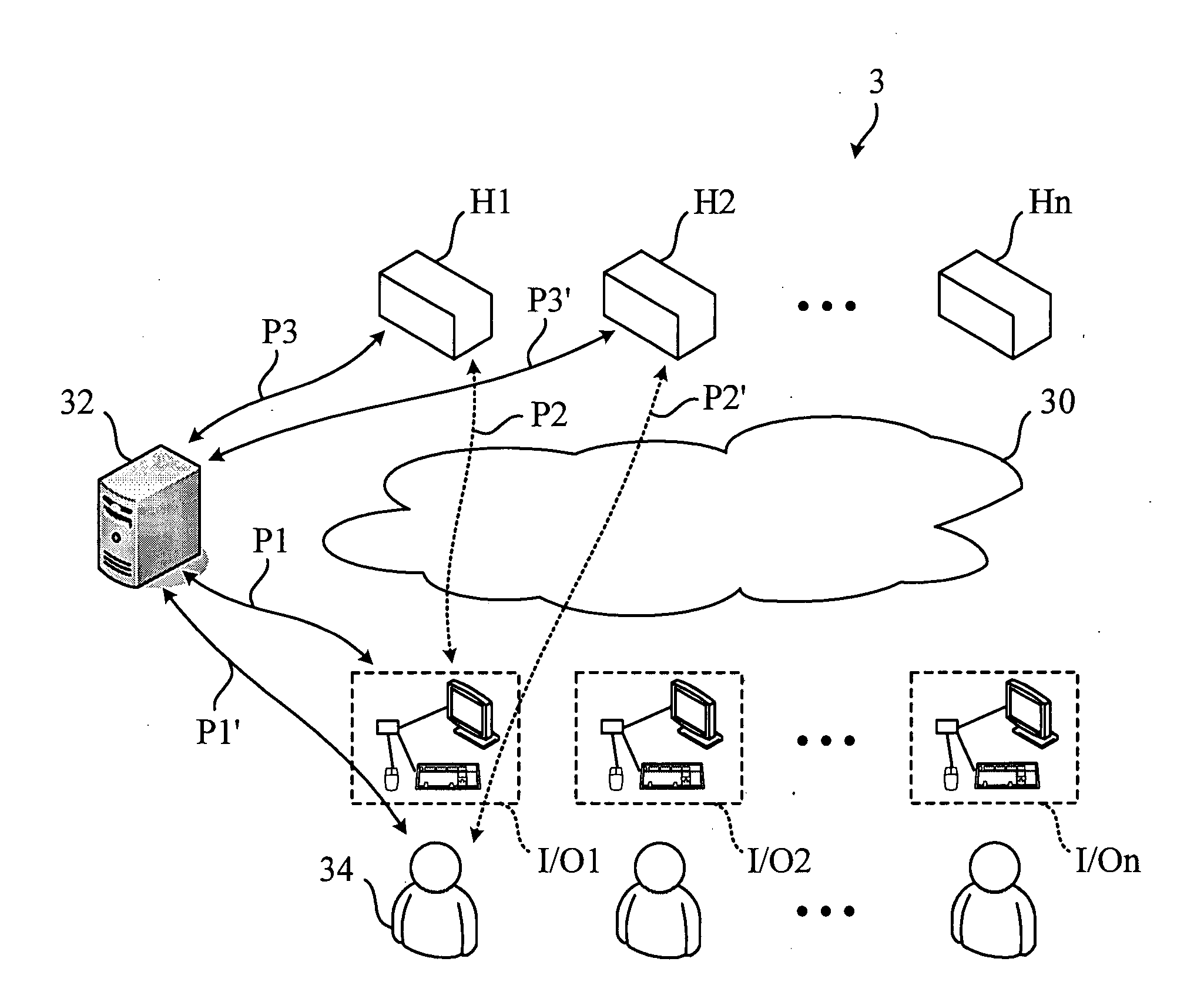
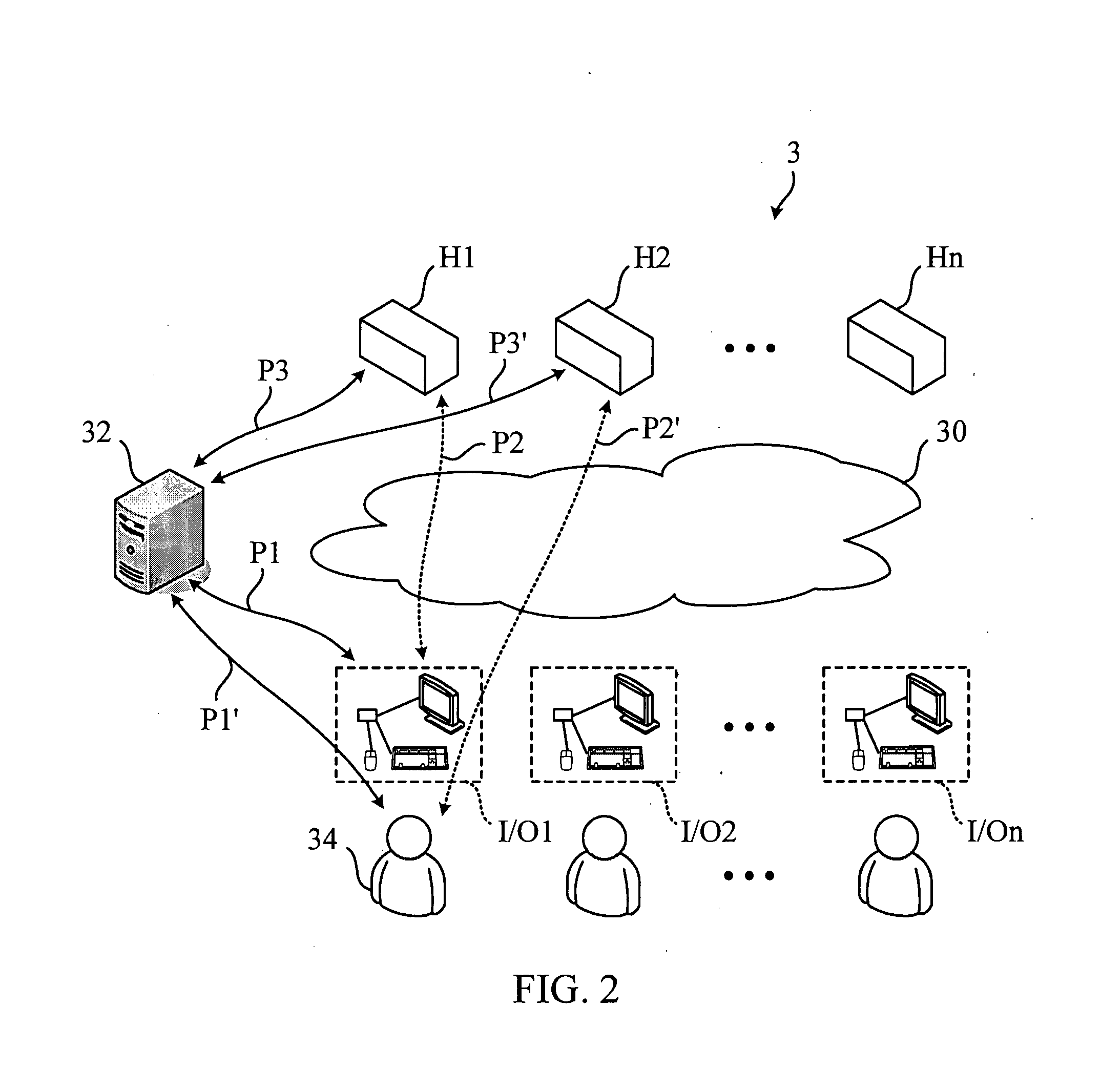
[0015]Referring to FIG. 2, FIG. 2 is a schematic diagram illustrating an infrastructure of a centralized computer system 3 according to a preferred embodiment of the invention. The centralized computer system 3 comprises a network 30, a plurality of hosts H1˜Hn, a plurality of I/O peripherals I/O1˜I/On, and a hierarchical server 32. In this embodiment, the hierarchical server 32 complies with but is not limited to a Lightweight Directory Access Protocol (LDAP). In this embodiment, each host H1˜Hn has a plurality of operating functions, wherein these operating functions comprise at least one selected from a group consisting of: console redirection, audio redirection, keyboard and mouse redirection, virtual storage redirection, monitoring and controlling, and other operating functions.
[0016]In the invention, a hierarchical directory is stored in the hierarchical service 32. The hierarchical directory is used for defining a first connecting relation for each host H1˜Hn and each set of I/O peripherals I/O1˜I/On and for defining a first authority for each set of I/O peripherals related to each host H1˜Hn. The first connecting relation comprises a first user name and a first password corresponding to the first user name. For example, if the first connecting relation exists between the host H1 and the set of I/O peripherals I/O1, the set of I/O peripherals I/O1 can be used to operate the host H1 via the network 30. The first user name and the first password are stored in the set of I/O peripherals I/O1 and cannot be modified. Additionally, the first authority allows the set of I/O peripherals I/O1 to operate at least one of the operating functions of the host H1 via the network 30.
[0017]Furthermore, as shown in FIG. 2, if an end user 34 wants to use the set of I/O peripherals I/O1 to operate the host H1, the set of I/O peripherals I/O1 can utilize the predetermined first user name and the predetermined first password to login the hierarchical server 32 (as the transmitting path P1 shown in FIG. 2). According to the first connecting relation defined in the hierarchical directory, the set of I/O peripherals I/O1 can connect with the host H1. Afterward, the set of I/O peripherals I/O1 transmits the first user name and the first password to the host H1 (as the transmitting path P2 shown in FIG. 2). Finally, the host H1 utilizes the first user name and the first password to login the hierarchical server 32 (as the transmitting path P3 shown in FIG. 2), so as to obtain the first authority. Whereby, according to the first authority, the set of I/O peripherals I/O1 can be used to operate at least one of the operating functions of the host H1 via the network 30. It should be noted that the service manager can define the first authority according to the capacity of each end user.
[0018]In this embodiment, the service manager can also selectively define the second connecting relation for each host H1˜Hn and at least one end user and selectively define a second authority for each end user related to each host H1˜Hn in the hierarchical directory. The second connecting relation comprises a second user name and a second password corresponding to the second user name. For example, if the second connecting relation exists between the host H2 and the end user 34, the end user 34 can use any set of I/O peripherals I/O1˜I/On to operate the host H2 via the network 30, even if the first connecting relation is absent between any set of I/O peripherals I/O1˜I/On and the host H2. In other words, due to the absence of the second connecting relation between the host H1 and the end user 34, the end user 34 can only use the set of I/O peripherals having the first connecting relation related to the host H1 to operate the host H1 via the network 30.
[0019]Moreover, as shown in FIG. 2, if the end user 34 wants to use the set of I/O peripherals I/O1 to operate the host H2, the end user 34 can use the set of I/O peripherals I/O1 to input the second user name and the second password to login the hierarchical server 32 (as the transmitting path P1′ shown in FIG. 2). According to the second connecting relation defined in the hierarchical directory, the connection between the set of I/O peripherals I/O1 and the host H2 is allowed. Afterward, the set of I/O peripherals I/O1 transmits the second user name and the second password to the host H2 (as the transmitting path P2′ shown in FIG. 2). Finally, the host H2 utilizes the second user name and the second password to login the hierarchical server 32 (as the transmitting path P3′ shown in FIG. 2), so as to obtain the second authority. Whereby, according to the second authority, the end user 34 can use the set of I/O peripherals I/O1 to operate at least one of the operating functions of the host H2 via the network 30. It should be noted that the service manager can define the second authority according to the capacity of each end user.
[0020]Compared to the prior art, according to the centralized computer system and the pairing method of the invention, the service manager utilizes the hierarchical directory to define the connecting relation for each host and each set of I/O peripherals and the connecting relation for each host and each end user. Additionally, the service manager can utilizes the hierarchical directory to define the authority for each set of I/O peripherals related to the host and the authority for each end user related to the host. Therefore, the invention not only can reduce the burden on the server manager but also can avoid wasting network management resource.
[0021]With the example and explanations above, the features and spirits of the invention will be hopefully well described. Those skilled in the art will readily observe that numerous modifications and alterations of the device may be made while retaining the teaching of the invention. Accordingly, the above disclosure should be construed as limited only by the metes and bounds of the appended claims.

PUM

no PUM

Description & Claims & Application Information

We can also present the details of the Description, Claims and Application information to help users get a comprehensive understanding of the technical details of the patent, such as background art, summary of invention, brief description of drawings, description of embodiments, and other original content. On the other hand, users can also determine the specific scope of protection of the technology through the list of claims; as well as understand the changes in the life cycle of the technology with the presentation of the patent timeline. Login to view more.

Similar technology patents

Electrically operated bed and method for controlling same

ActiveUS20100011505A1reduce burden
Owner:PARAMOUNT BED CO LTD

Multiple function integrated circuit

InactiveUS20060075166A1reduce burden
Owner:SIGMATEL

Classification and recommendation of technical efficacy words

  • reduce burden
  • avoid waste

Navigation system

InactiveUS20060041372A1reduce burdensafety be ensure
Owner:AISIN AW CO LTD

Remote processor

InactiveUS20050055547A1reduce burden
Owner:KONICA MINOLTA BUSINESS TECH INC

Blood purification device

ActiveUS20040129616A1reduce burdenreduced period of time
Owner:NIKKISO COMPANY

Packaging substrate and fabrication method thereof

ActiveUS20100319966A1readily separateavoid waste
Owner:UNIMICRON TECH CORP

Microplate liquid handling system

InactiveUS7169362B2avoid wasteminimal time
Owner:HITACHI KOKI CO LTD

Modular safety railing system

InactiveUS20060054393A1avoid wasteeasily erect
Owner:EISENKREIN LARRY
Why Eureka
Try Eureka