

Panel Installation Set and Method of Installing Panel Using the Same
- Summary
- Abstract
- Description
- Claims
- Application Information
AI Technical Summary
Benefits of technology
Problems solved by technology
Method used
Image

Examples
first embodiment
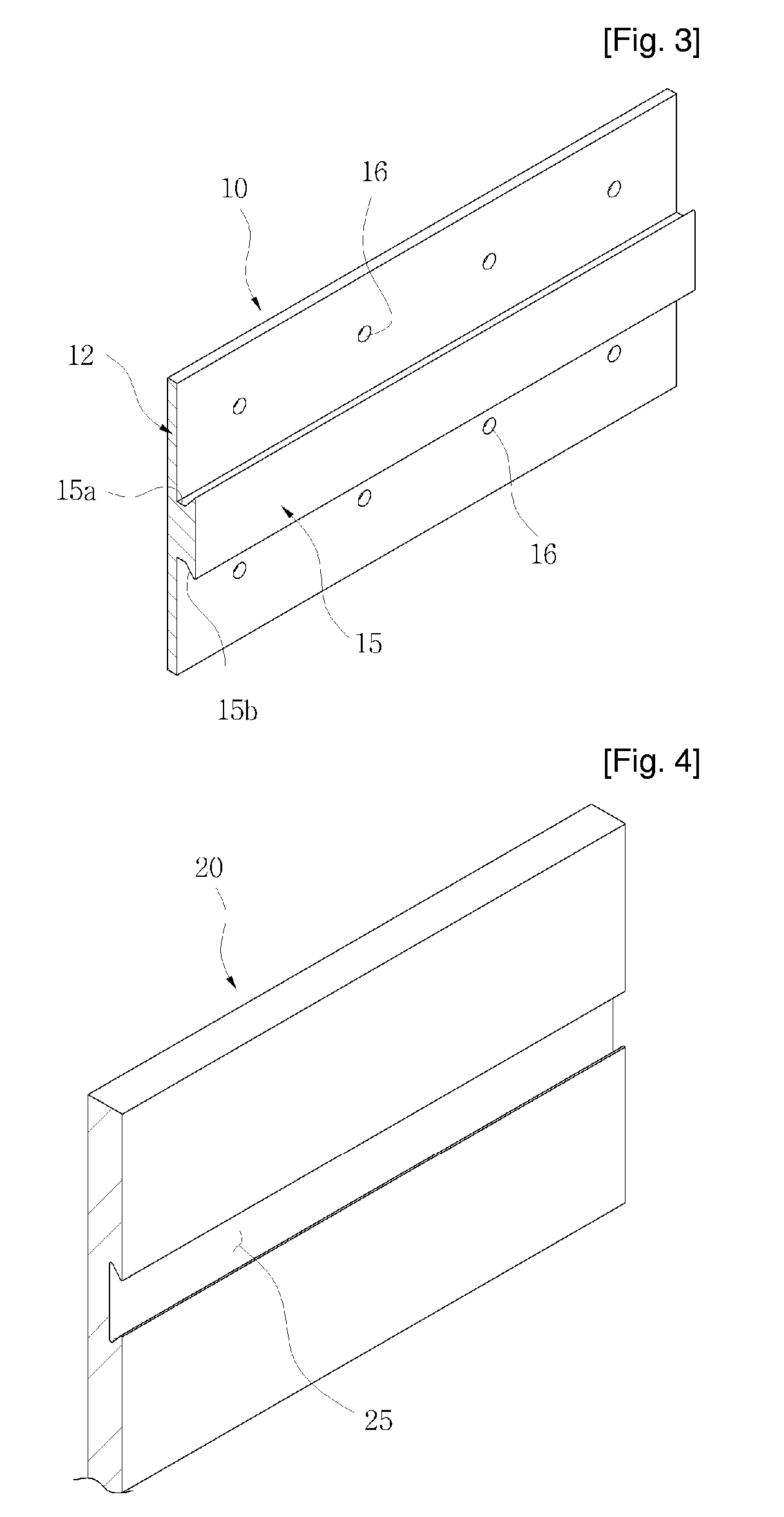
[0033]FIG. 3 through FIG. 6 illustrate a panel installation set according to the present invention, in which FIG. 3 is a perspective view illustrating a support member, FIG. 4 is a perspective view illustrating a panel, FIG. 5 is a sectional view illustrating the panel installed on a wall of a building, and FIG. 6 is a sectional view illustrating the support member shown in FIG. 3.
[0034] Referring to FIG. 3 through FIG. 6, the support member 10 of the panel installation set according to the first embodiment has a coupling projection 15 serving as a coupling means. In more detail, as shown in FIG. 3, the support member 10 includes a substrate 12, at least one coupling projection 15 protruding from the surface of the substrate 12, and a plurality of insertion holes 16 into which coupling means 30 are inserted.
[0035] The panel 20 has a coupling groove 25 on the surface thereof, the coupling groove 25 serving as a coupling means and having a shape opposite to the shape of the coupling ...
second embodiment
[0047]FIG. 11 and FIG. 12 illustrate a panel installation set according to the present invention. FIG. 11 is a sectional view illustrating a panel 20 installed on a wall W of a building, and FIG. 12 is a sectional view illustrating the support member 10 and the panel 20.
[0048] Referring to FIG. 11 and FIG. 12, a coupling projection 15 for assembling a support member 10 and a panel 20 is integrated with the panel 20 into a single body. A coupling groove 25 engaging with the coupling projection 15 is provided to the support member 10. In more detail, the support member 10 comprises a substrate 12, and a protrusion 14 integrated with the substrate 12, and the coupling groove 25 is formed in the protrusion 14. The coupling projection 15 to be inserted into the coupling groove 25 protrudes from the surface of the panel 20 and has an insertion part 15b that extends outward from a main body of the coupling projection 15 and is tapered. The method of assembling the support member 10 and the...
third embodiment
[0049]FIG. 13 through FIG. 16 illustrate a panel installation set according to the present invention. FIG. 13 is a sectional view illustrating the sequence of assembling a support member 10 and a panel 20, FIG. 14 is a front view illustrating the support member 10 fixed to a base frame F on a wall of a building, FIG. 15 is a partial sectional view taken along a first direction and illustrating the assembled panel 20 and the support member 10, and FIG. 16 is a sectional view taken along a direction different from the view in FIG. 15.
[0050] Referring to FIG. 13, the support member 10 has a coupling projection 15 and the panel 20 has a coupling groove 25. The coupling projection 15 and the coupling groove 25 have a structure such that the coupling projection 15 can be inserted into the coupling groove 25 in the X direction. In more detail, the width D of an end portion of the coupling projection 15 is the same as or smaller than the width D of an entrance portion of the coupling groove...
PUM
 Abstract
Description
Claims
Application Information