Device and method for efficiently converting volatile organic compounds
A volatile organic compound, high-efficiency technology, applied in chemical instruments and methods, separation methods, gas treatment, etc., can solve complex engineering problems and other problems, achieve the effect of long reaction life and device cost reduction
- Summary
- Abstract
- Description
- Claims
- Application Information
AI Technical Summary
Problems solved by technology
Method used
Image
Examples
Embodiment 1
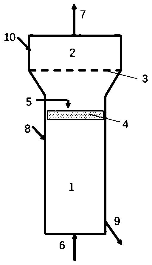
[0031] use as figure 1 The apparatus shown, wherein the height of the fluidized bed section 1 is twice the height of the fixed bed section 2. The porosity of the porous distribution plate 3 is 30%, and the diameter of a single hole is 1 mm. On the cross-section of the fluidized bed section 1 0.5 m below the porous distribution plate 3, a 1 cm thick wire mesh layer 4 (platinum, with a porosity of 90%, and a single hole diameter of the wire mesh less than 0.01 mm) is set. At the central position of the perforated distribution plate 3 and the wire mesh layer 4, a water vapor injection pipe 5 (opening downward, facing the wire mesh layer 4) is arranged.
[0032] Through the catalyst inlet 8 of the fluidized bed section, a nanometer metal-supported catalyst (10% Fe-90% alumina, 1 nm in grain size) with an average particle size of 0.05 mm is charged into the fluidized bed section 1 . Through the catalyst inlet 10 of the fixed bed section, a nanometer metal-supported catalyst (90% ...
Embodiment 2
[0037] use as figure 1The apparatus shown, wherein the height of the fluidized bed section 1 is 5 times the height of the fixed bed section 2. The porosity of the porous distribution plate is 70%, and the diameter of the single hole is 8mm. On the cross-section of the fluidized bed section 1 1 m below the porous distribution plate 3, a 3 cm thick wire mesh layer 4 (stainless steel, with a porosity of 95%, and a single hole diameter of the wire mesh less than 0.01 mm) is set. At the central position of the perforated distribution plate 3 and the wire mesh layer 4, five water vapor injection pipes 5 (opening downwards, facing the wire mesh layer 4) are arranged.
[0038] Through the catalyst inlet 8 of the fluidized bed section, a nanometer metal-supported catalyst (10% Fe-90% alumina, grain size 20nm) with an average particle size of 0.5 mm is charged into the fluidized bed section 1 . Through the catalyst inlet 10 of the fixed bed section, a nanometer metal-supported catalys...
Embodiment 3
[0043] use as figure 1 The apparatus shown, wherein the height of the fluidized bed section 1 is three times the height of the fixed bed section 2. The porosity of the porous distribution plate 3 is 60%, and the diameter of a single hole is less than 3mm. On the fluidized bed section 1 cross-section 0.8m below the porous distribution plate 3, a 2cm-thick wire mesh layer 4 (nickel, porosity 92%, single hole diameter of the wire mesh less than 0.01mm) is set. At the central position of the perforated distribution plate 3 and the wire mesh layer 4, four water vapor injection pipes 5 (opening downwards, facing the wire mesh layer 4) are arranged.
[0044] Through the catalyst inlet 8 of the fluidized bed section, the nanometer metal supported catalyst (30% Fe-30% Co-10% Mo-30% magnesia, crystal grain is 5nm) with an average particle diameter of 0.1-0.3 mm is loaded into the fluidized bed In bed section 1. Through the catalyst inlet 10 of the fixed bed section, a nanometer metal...
PUM
| Property | Measurement | Unit |
|---|---|---|
| Thickness | aaaaa | aaaaa |
| Porosity | aaaaa | aaaaa |
| Porosity | aaaaa | aaaaa |
Abstract
Description
Claims
Application Information
 - R&D
- Intellectual Property
- Life Sciences
- Materials
- Tech Scout
- Unparalleled Data Quality
- Higher Quality Content
- 60% Fewer Hallucinations
Browse by: Latest US Patents, China's latest patents, Technical Efficacy Thesaurus, Application Domain, Technology Topic, Popular Technical Reports.
© 2025 PatSnap. All rights reserved.Legal|Privacy policy|Modern Slavery Act Transparency Statement|Sitemap|About US| Contact US: help@patsnap.com

