Intelligent, full-featured diesel engine exhaust treatment system

Active Publication Date: 2005-03-31
TRIVISION TECH TAIWAN
View PDF8 Cites 2 Cited by
  • Summary
  • Abstract
  • Description
  • Claims
  • Application Information

AI Technical Summary

Benefits of technology

[0016] According to this invention, the exhaust detecting device is provided in the exhaust treatment paths to allow omnibearing detection of the exhaust data discharged by the engine, such as temperature, pressure, flow rate, light impermeability, and the existence of hydrocarbons, carbon monoxides, sulfides, and nitrides. The microcomputer processor would then determine the state of contaminants in the engine exhaust based on the exhaust data to transmit a command for selecting an appropriate exhaust treatment path which can optimize the treatment effects, Such that the soot particles, hydrocarbons and carbon monoxide in the engine exhaust can pass through the soot filters and catalyst converters, r

Problems solved by technology

Even though such soot filters can indeed achieve the intended filtering effects, such a conventional measure of treating engine exhaust by filters involves the shortcomings that, (1) the soot filters can only filter soot and the filter medium requires frequent regeneration and cleaning, such that they cannot accommodate to the extended operation of engines; and (2) the pressure drop resulted from the ceramic filter element configured of such honeycombed walls is relatively high, and the cost for installing a system having a large number of conventional soot filters is about 5 to 15 folds of that using catalyst convert

Method used


Image

  • Intelligent, full-featured diesel engine exhaust treatment system
  • Intelligent, full-featured diesel engine exhaust treatment system
  • Intelligent, full-featured diesel engine exhaust treatment system

Examples


Example

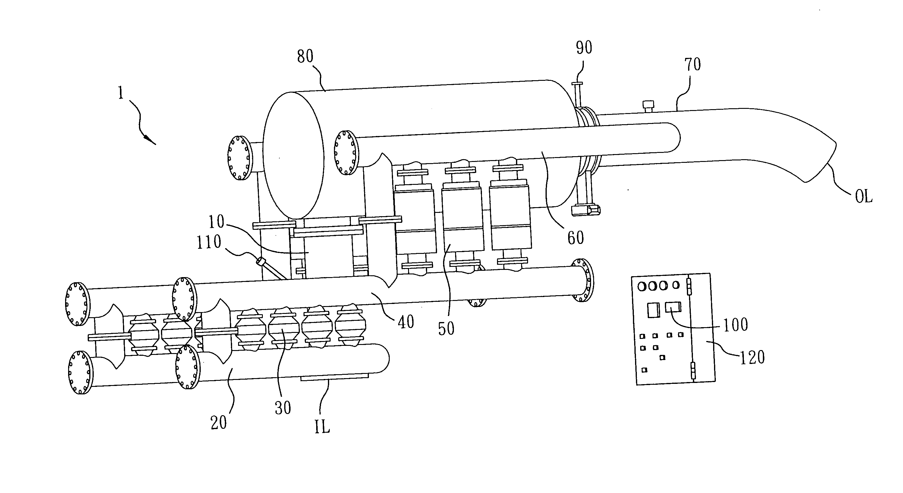
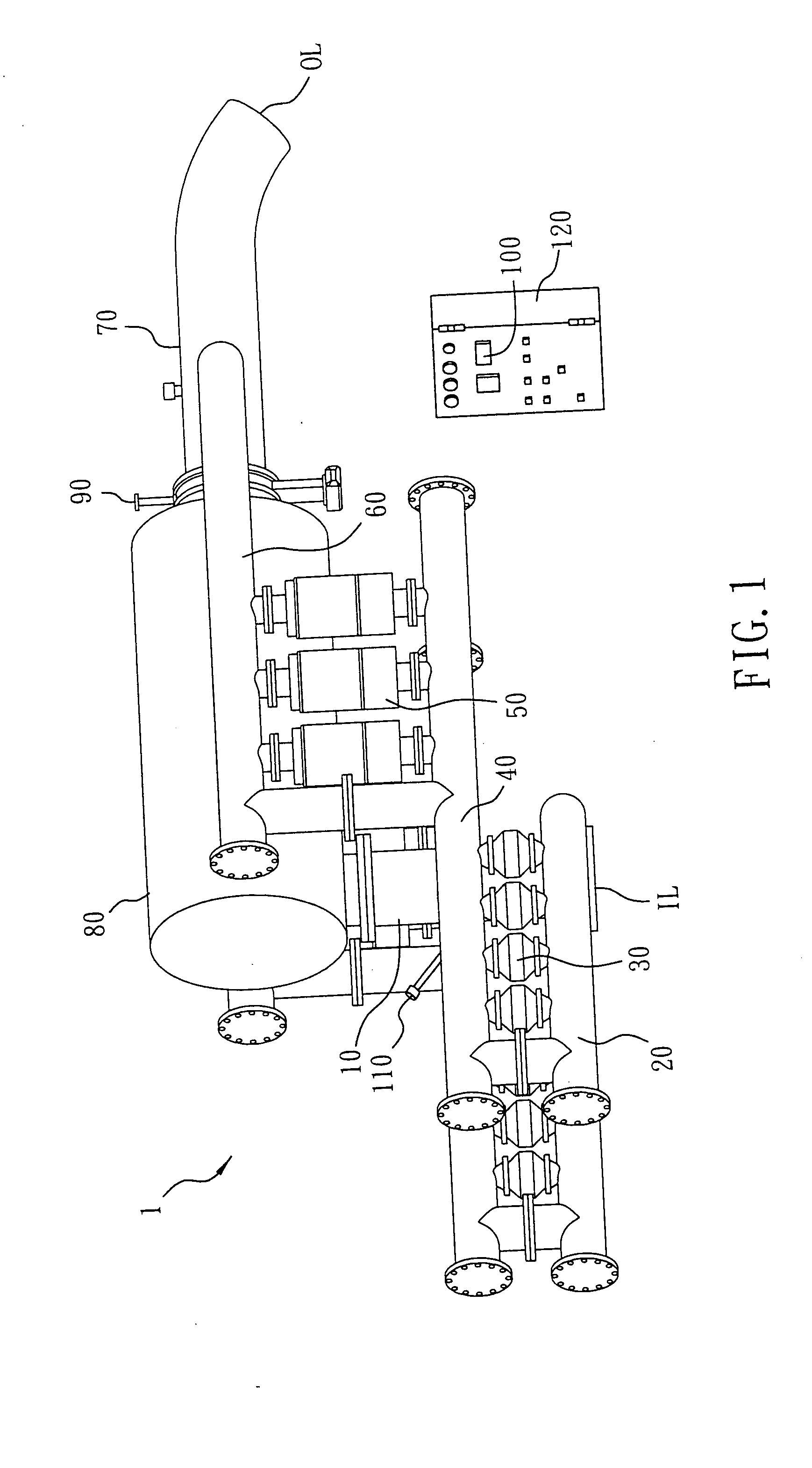
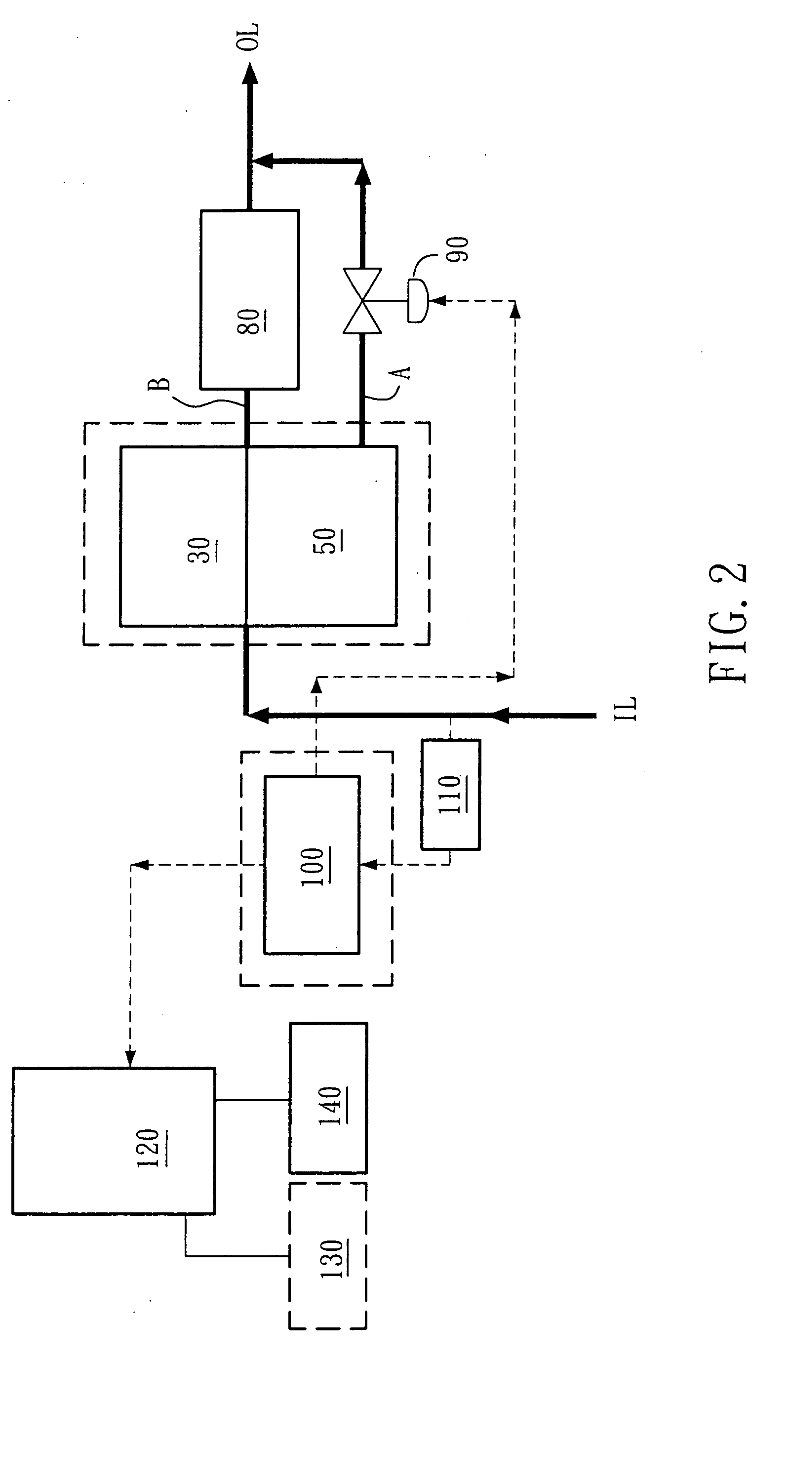
[0022]FIG. 1 is a schematic view illustrating an arrangement of this invention in a horizontally symmetrical configuration. The intelligent, full-featured diesel engine exhaust treatment system 1 as illustrated generally includes an exhaust flowing zone constructing of plural components 10, 20 . . . , 80, which will be described later, a microcomputer processor 100, and an exhaust detecting device 110 provided between the exhaust flowing zone and the microcomputer processor 100.

[0023] The exhaust flowing zone preferably includes: an intermediate communicating pipe 10, at least one lower collection tube 20, at least one catalyst converter array 30, at least one intermediate collection tube 40, at least one soot filter array 50, at least one upper collection tube 60, a main exhaust pipe 70, and a muffler 80.

[0024] The intermediate communicating pipe 10 includes an inlet IL connected to an engine outlet for receiving non-treated exhaust discharged by the engine. The at least one lowe...


PUM


Abstract

Disclosed is an intelligent, full-featured diesel engine exhaust treatment system, including: an exhaust flowing zone, a microcomputer processor, and an exhaust detecting device, the exhaust flowing zone defining a first exhaust treatment path and a second exhaust treatment path, the microcomputer processor selectively employing a soot filter and a catalyst converter to purify the engine exhaust based on the state of contaminants in the engine exhaust as detected by the exhaust detecting device.

Description

CROSS-REFERENCES TO RELATED APPLICATIONS [0001] Not Applicable STATEMENT REGARDING FEDERALLY SPONSORED RESEARCH OR DEVELOPMENT [0002] Not Applicable DESCRIPTION [0003] 1. Field of Invention [0004] This invention relates to an intelligent, full-featured diesel engine exhaust treatment system to be implemented in a power generator or dynamic UPS. [0005] 2. BACKGROUND [0006] Diesel engine exhaust treatment system is a technology that has been widely implemented in the industry, and is mainly implemented in filtering and treating two types of exhaust, including: (1) soot particles (particle contaminants); and (2) a mixture of hydrocarbons and carbon monoxides (gaseous contaminants). For example, TW324467Y disclosed an exhaust treatment apparatus, including a hollow container; a filter assembly coated with catalyst to a surface thereof and formed with an intake compartment; a retaining bracket; a heater capable of generating heat; and an intake pipe consisting of a long tube and a short ...

Claims


Application Information

Patent Timeline
IPC IPC(8): F01N3/023F01N3/20F01N13/04
CPCF01N3/023F01N13/011F01N3/2053
Inventor HSU, PAUL
Owner TRIVISION TECH TAIWAN
Why Eureka
Try Eureka