This helps you quickly interpret patents by identifying the three key elements:
Problems solved by technology
Method used
Benefits of technology
Benefits of technology
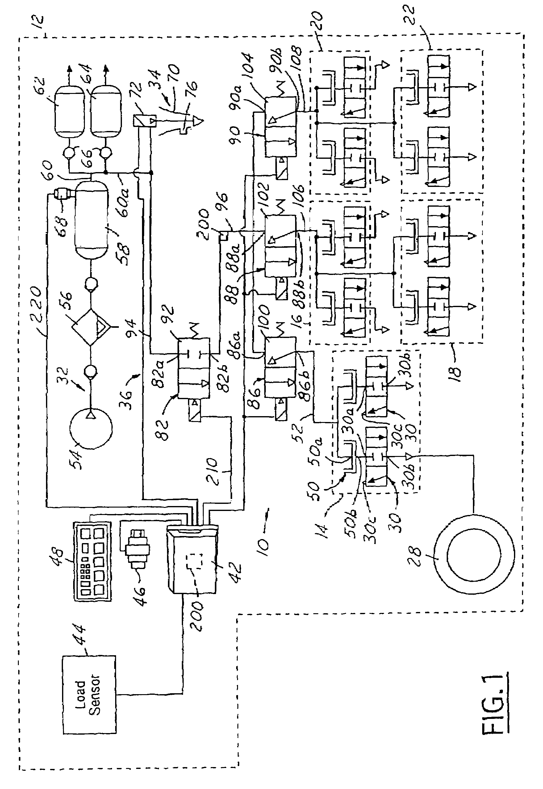
[0007]The present invention is directed toward increasing the pressure in one or more tires of a vehicle. The preferred method comprises monitoring the dynamic pressure of air flowing through a fluid control circuit to one or more tires of a vehicle that are below a target pressure. When the dynamic pressure reaches a predetermined amount over the target pressure, a valve stops the f
Problems solved by technology
The prior art systems can be disadvantageous because often they have no means to prevent the highly pressurized fluid from the source reaching tires that do not need to be inflated.
This can result in the incremental over inflation of tires that are already at their target or desired pressure.
Over time, this can raise tire pressures close to the pressure of the source of fluid.
Generally, over inflated tires are undesirable since they wear more quickly, they can change the ride characteristics of the vehicle and they are prone to failure.
Tire failure can be catastrophic for a vehicle.
It can be appreciated that providing larger and larger bursts of highly pressurized air can result in the over inflation of tires that do not need additional air since typically the under inflated tire or tires cannot accept all the air provided in such a high pressure burst.
This patent also fails to disclose means to prevent the pulses of compressed air from reaching one or more tires that do not need to be inflated.
Method used
Image
Click on the blue label to locate the original text in one second.
Reading with bidirectional positioning of images and text.
Examples
Embodiment Construction
[0007]The present invention is directed toward increasing the pressure in one or more tires of a vehicle. The preferred method comprises monitoring the dynamic pressure of air flowing through a fluid control circuit to one or more tires of a vehicle that are below a target pressure. When the dynamic pressure reaches a predetermined amount over the target pressure, a valve stops the flow of air. The air introduced into the fluid control circuit is permitted to flow toward the one or more tires. The valve opens again and, when the dynamic pressure builds to the predetermined amount, the valve again closes. The above steps are rapidly repeated so that one or more tires below the target pressure are inflated, but tires already at the target pressure are not inflated.
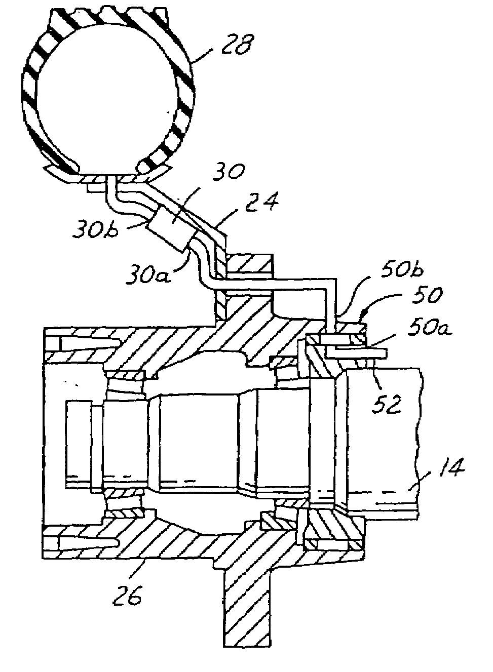
BRIEF DESCRIPTION OF THE DRAWINGS
[0008]The above, as well as other advantages of the present invention, will become readily apparent to those skilled in the art from the following detailed description when considered in the ...
PUM
Abstract
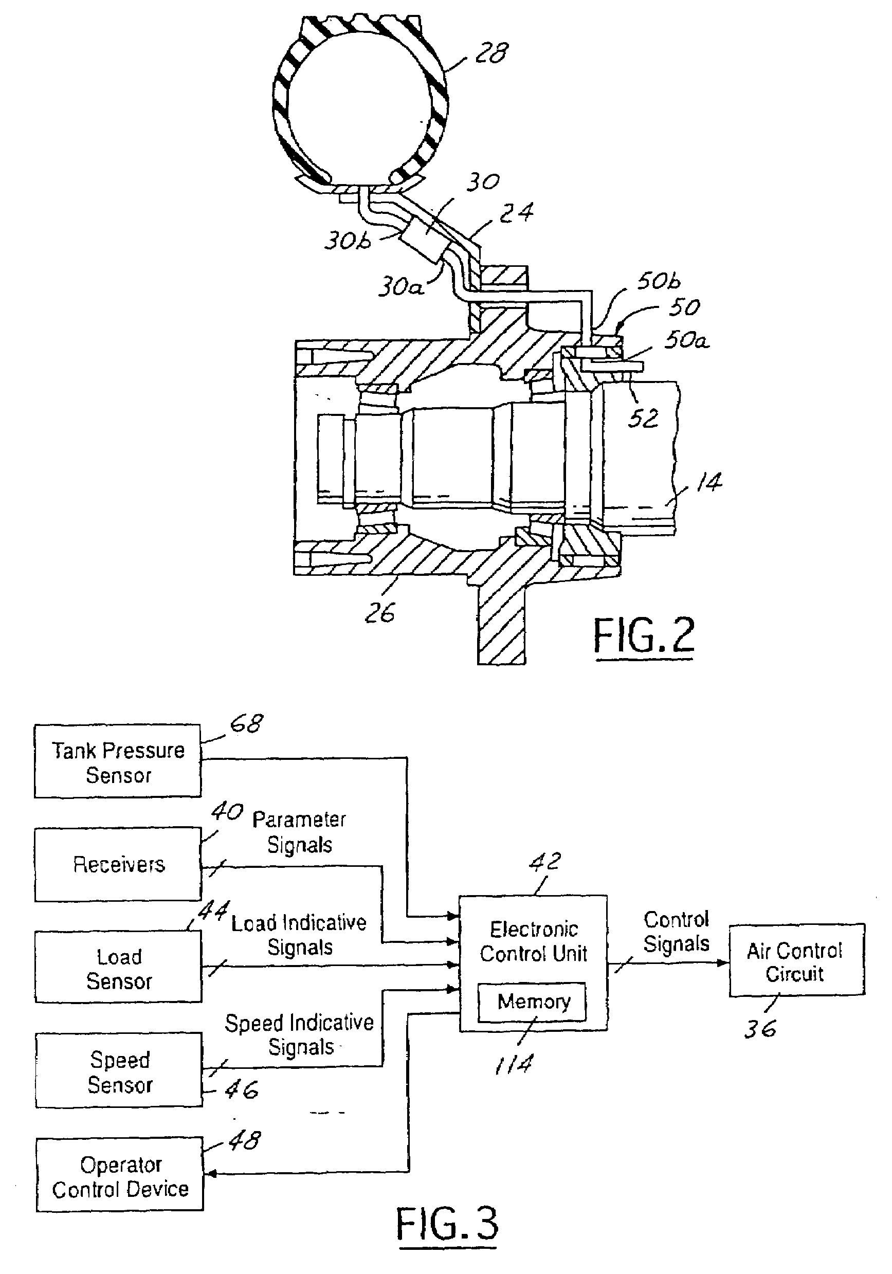
A tire inflation method is disclosed for moving air through a fluid control circuit to at least one tire that is below a target pressure. The dynamic pressure of the moving air in the fluid control circuit is monitored. A pressure control valve in the fluid control circuit is cycled on and off to prevent the dynamic pressure from reaching a predetermined amount over the target pressure.
Description
FIELD OF THE INVENTION[0001]The present invention relates to a method to inflate tires of a vehicle.BACKGROUND OF THE INVENTION[0002]Tire inflation methods, also known as on-board inflation methods and traction methods, are well known, as may be seen by reference to the following U.S. patent Nos.: U.S. Pat. Nos. 5,516,379; 5,313,995; 5,273,064; 5,253,687; 5,180,456; 5,179,981; 5,174,839; 5,121,774; 4,924,926; 4,922,946; 4,917,163; 4,893,664; 4,883,106; 4,883,105; 4,825,925; 4,782,879; 4,754,792; 4,724,879; 4,678,017; 4,640,331; and 4,619,303. The entire disclosures of each of these patents are incorporated herein.[0003]Typically, such systems comprise a source of pressurized fluid, a circuit leading from the source of pressurized fluid to the tires of a vehicle and a means to control the amount of fluid flowing from the source to the tires.[0004]The prior art systems can be disadvantageous because often they have no means to prevent the highly pressurized fluid from the source reach...
Claims
Application Information
Patent Timeline
Application Date:The date an application was filed.
Publication Date:The date a patent or application was officially published.
First Publication Date:The earliest publication date of a patent with the same application number.
Issue Date:Publication date of the patent grant document.
PCT Entry Date:The Entry date of PCT National Phase.
Estimated Expiry Date:The statutory expiry date of a patent right according to the Patent Law, and it is the longest term of protection that the patent right can achieve without the termination of the patent right due to other reasons(Term extension factor has been taken into account ).
Invalid Date:Actual expiry date is based on effective date or publication date of legal transaction data of invalid patent.

