Planetary gear bearing arrangement

a gear bearing and gear bearing technology, applied in the direction of bearings, shafts, engine fuctions, etc., can solve the problems of high effort, prone to wear, and edge pressure, and achieve the effect of more resistance to wear

Active Publication Date: 2018-08-14
SCHAEFFLER TECH AG & CO KG
View PDF49 Cites 8 Cited by
  • Summary
  • Abstract
  • Description
  • Claims
  • Application Information

AI Technical Summary

Benefits of technology

[0008]To achieve this object, it is provided that, according to the present invention, in a planetary gear bearing system of the type mentioned at the outset, one of the two antifriction layers is produced on a surface having a domed profile, at least in sections, for the purpose of reducing the edge pressure in the sliding area.
[0018]It is particularly advantageous in this case, if the axial disk also have an antifriction layer in the form of a deposited hard material layer, which runs on an antifriction layer formed on the planet carrier or the planet wheel in the form of a hardened surface layer. This means that the corresponding, advantageous material pairing of hard material layer / hardened surface layer according to the present invention, which is wear-resistant, is also provided on the axial bearing side. In combination with the edge recess according to the present invention via the domed surface, an extreme wear resistance consequently also results in the axial friction bearing area, whether during normal sliding operation or with respect to reducing excess edge pressures.

Problems solved by technology

This means that an edge pressure occurs in the friction bearing area, which is conducive to wear.
If an uneven introduction of force occurs, due to operation, and a tilting moment results as a consequence, this stresses, in particular the friction partner made of white metal or bronze, since it is the softer friction partner within the material pairing and is therefore more susceptible to wear.
If the planetary gearset has a large design, as is generally the case in gearsets which are used in the area of wind turbines, considerable tilting moments result, which are conducive to wear.
In large planetary gearsets, in particular, this is problematic, since a worn bearing component may not be readily replaced, or if this is possible at all, only with a great deal of effort.
In this material pairing, a frequent operation of the friction bearing in the mixed-friction area, results in an early scooping out of the wear volume, possibly even damage and thus an early failure of the friction bearing, due to the high surface wear on the friction partner made of white metal or bronze.
However, the area of the mixed friction described at the outset is traversed by frequently changing, in particular low rotational speeds and high dynamics of the bearing loads, in particular, each time the friction bearing starts and stops.
If a planetary gearset is thus used in applications in which a bearing frequently starts, corresponding high bearing loads are present, which are conducive to wear.
Consequently, very little friction action occurs during sliding, resulting in little heat development compared to friction bearing systems of a conventional hydrodynamic design, based on bronze and white metal materials.
If a material pairing of this type is thus used, an extremely wear-free operation results when operating under normal load.
If there is an uneven load introduction or tilting of the planet wheel relative to the planet axis, this also does not have a wear-conducive effect, since the surface having a dome profile reduces the edge pressure.
However, it is compensated by the corresponding surface profiling, which means that excess edge pressure, which would be conducive to wear, also does not exist in the axial friction bearing area.

Method used


Image

  • Planetary gear bearing arrangement
  • Planetary gear bearing arrangement
  • Planetary gear bearing arrangement

Examples


Embodiment Construction

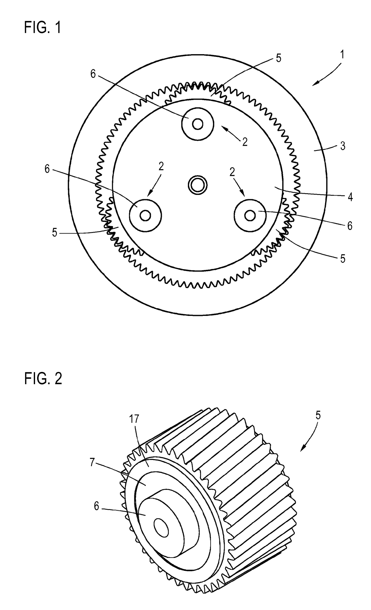
[0036]FIG. 1 shows a planetary gearset 1 according to the present invention, including a total of three planetary gear bearing systems 2 according to the present invention. Planetary gearset 1 includes an annulus wheel 3, which has an inner gearing, as well as a planet carrier 4, which has three planet wheels 5, which are rotatably supported thereon and mesh with annulus wheel 3 in the known way via their outer gearings. Each planet wheel 5 is supported in the manner according to the present invention on a bearing axis 6, which is fixedly connected to planet carrier 4. The planetary gearset is driven via a sun wheel, which meshes with planet wheels 5 and is not illustrated in greater detail.

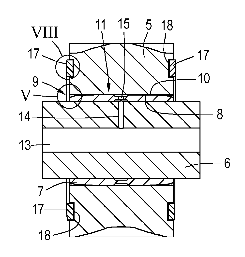
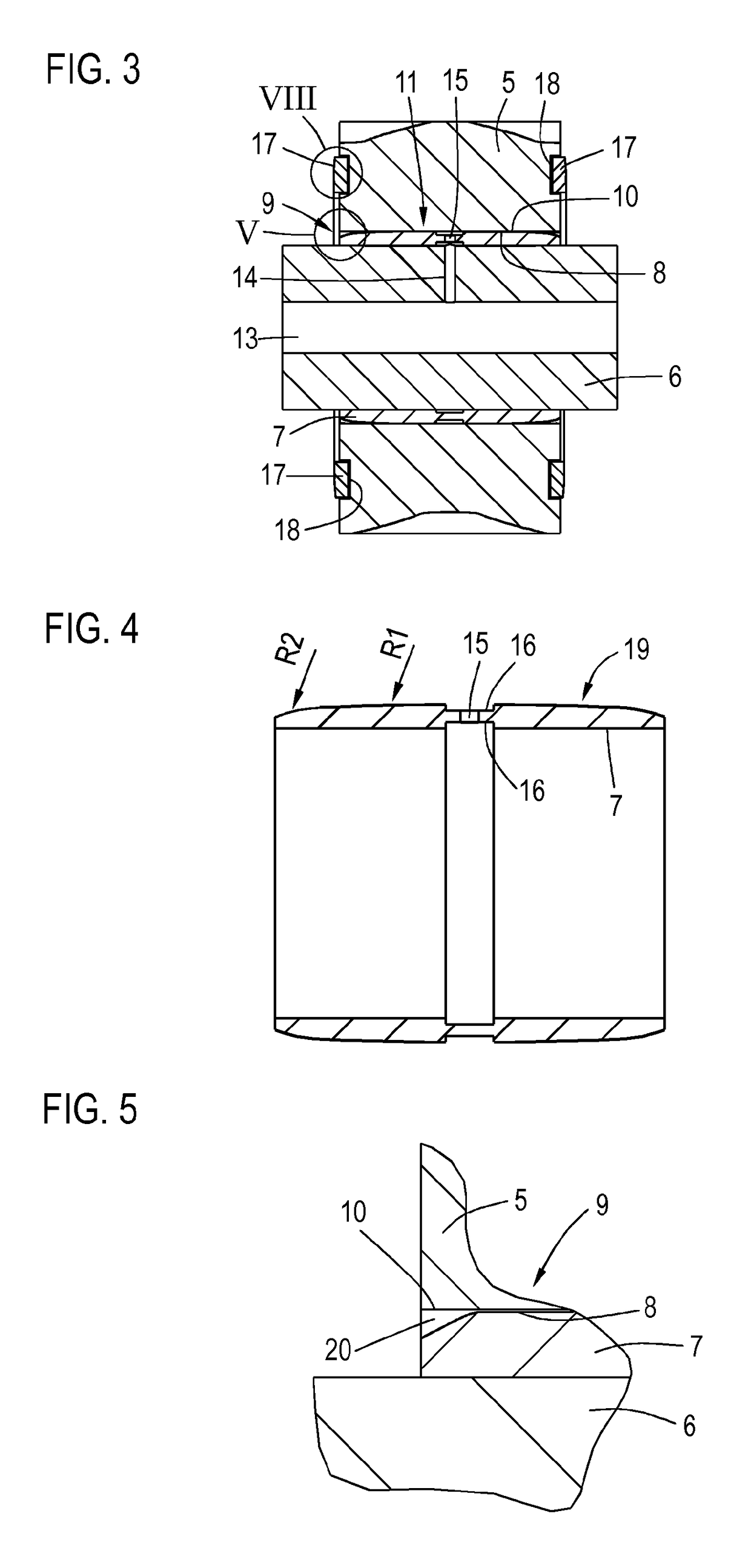
[0037]FIGS. 2 and 3 show a first specific embodiment of a planet wheel bearing. FIG. 2 shows planet wheel 5 as well as bearing axis 6, which is fastened to planet carrier 4 known from FIG. 1 in a way which is known per se. A sleeve 7 is fastened to bearing axis 6. Sleeve 7 has a first antifrictio...


PUM


Abstract

A planetary gear bearing arrangement, including a planet carrier provided with a fixed bearing axis on which a planet gear is rotatably mounted via a sliding bearing that has a first antifriction layer on the axis side and a second antifriction layer on the gear side, wherein one of the two antifriction layers (8, 11) is created on a surface (10, 19) which is at least partially domed in the sliding region to reduce the edge pressure.

Description

[0001]The present invention relates to a planetary gear bearing system, including a planet carrier, on which a fixed bearing axis is provided, on which a planet wheel is rotatably mounted via a friction bearing, which has a first antifriction layer provided on the axis side and a second antifriction layer provided on the wheel side.BACKGROUND[0002]A planetary gear bearing system is typically used in a planetary gearset. A planetary gearset of this type typically includes at least one sun wheel, an annulus wheel and a planet carrier, on which at least one planet wheel is rotatably mounted on a bearing axis. The sun wheel drives, for example, the planet wheel, at least multiple, for example three, planet wheels being distributed equidistantly, which are driven together via the sun wheel. The planet wheel(s) mesh(es) with the annulus wheel, so that the corresponding gear ratio occurs.[0003]Methods are known for rotatably mounting the planet wheel on the bearing axis via a friction bear...

Claims


Application Information

Patent Timeline
Patent Type & Authority Patents(United States)
IPC IPC(8): F16C33/10F16C33/04F16C23/04F16C17/02F16H57/08F03D15/00F16C17/04
CPCF16C33/1055F16C17/02F16C23/041F16C33/046F03D15/00F16H2057/085F05B2260/40311F16C17/04F16C2223/10F16C2361/61F05B2240/50F16C33/08F16H57/08F16C17/26F16C2202/04F16C2360/31Y02E10/72F03D80/70
Inventor GUETTLER, ALEXANDERPLOGMANN, MICHAELFORSTNER, CHRISTIANCLAUS, SVEN
Owner SCHAEFFLER TECH AG & CO KG
Why Eureka
Try Eureka