High-pressure pump

A high-pressure pump and pump piston technology, applied in the field of high-pressure pumps, can solve the problems of increased wear and tear in the contact area, and achieve the effects of reduced weight and good pressing force characteristics

Inactive Publication Date: 2012-05-23
ROBERT BOSCH GMBH
View PDF8 Cites 0 Cited by
  • Summary
  • Abstract
  • Description
  • Claims
  • Application Information

AI Technical Summary

Problems solved by technology

This contact area is therefore also subject to increased wear

Method used


Image

  • High-pressure pump
  • High-pressure pump
  • High-pressure pump

Examples


Embodiment Construction

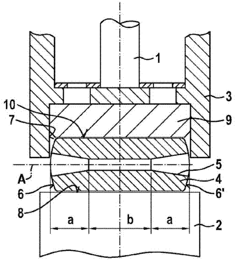
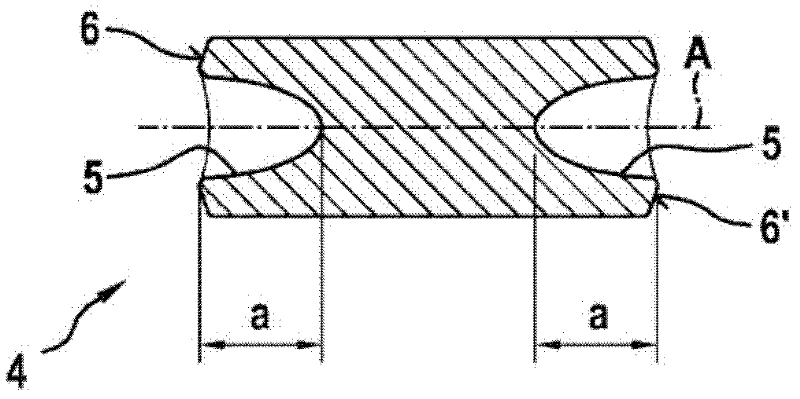
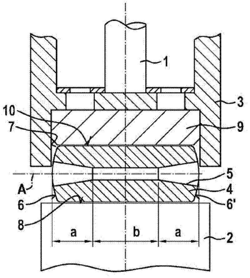
[0019] exist figure 1 The pump part of the high-pressure pump according to the invention shown in section in the middle has a pump piston 1 which is indirectly supported via a roller 4 on a cam 2 of a drive shaft (not shown). The roller 4 is received at least partially in a push rod 3 which has a pot-shaped end. For additional support of the roller 4 , a roller shoe 9 is also provided, which is arranged between the push rod 3 and the roller 4 . The rotation of the drive shaft is transmitted to the roller 4 through the cam 2, and the outer peripheral side of the roller rolls on the cam 2. The outer peripheral side of the cam 2 thus forms a rolling surface 8 . Due to the eccentricity of the cam 2 relative to the longitudinal axis of the drive shaft its rotational movement is converted into a linear movement of the pump piston 1 by the roller 4 held in the push rod 3 . In this case, especially the contact area of ​​the roller 4 on the push rod 3 and on the running surface of t...


PUM


Abstract

The invention relates to a high-pressure pump for a fuel injection device of an internal combustion engine, comprising at least one pump element having a pump piston (1) that can be driven via a cam (2) or eccentric disk of a drive shaft in a stroke movement, wherein the pump piston (1) is directly supported via a tappet (3) and a roller (4) on the cam (2) or eccentric disk of the drive shaft. According to the invention, the roller (4) comprises at least one central bore (5), which extends along the longitudinal axis (A) of the roller (4) and comprises at least one cone-shaped, partially spherical and / or partially elliptical sub-section (a) for forming an inner contour.

Description

[0001] current technology [0002] The invention relates to a high-pressure pump for a fuel injection system of an internal combustion engine having the features of the preamble of claim 1 . Background technique [0003] Such a high-pressure pump is known, for example, from laid-open document DE 10 2006 041 673 A1. The high-pressure pump described therein has a drive shaft with at least one cam or eccentric and at least one pump part, which includes a pump piston that can be driven to and fro by the cam or eccentric of the drive shaft. The pump piston is supported here on a cam or eccentric of the drive shaft via a support element and a roller mounted rotatably in this support element. The support part and the roller are jointly accommodated in a cup-shaped push rod for support, wherein a contact area is formed between the roller and the cup-shaped push rod and / or the support part. Due to the rotational movement of the rollers, the contact area is subject to increased wear, ...

Claims


Application Information

Patent Timeline
Patent Type & Authority Applications(China)
IPC IPC(8): F02M59/44F02M59/10
CPCF02M59/44F02M59/102F02M59/10F04B1/04F04B9/04
Inventor F·伯金
Owner ROBERT BOSCH GMBH
Why Eureka
Try Eureka