Apparatus And Method for Material Distribution

a material moving apparatus and material technology, applied in the direction of snow cleaning, transportation and packaging, mechanical machines/dredgers, etc., can solve the problems of extremely maneuverable and nimble material moving apparatus, and achieve the effects of less pressure, more pressure, and convenient operation

Active Publication Date: 2012-11-22
JONES DAVID A
View PDF23 Cites 10 Cited by
  • Summary
  • Abstract
  • Description
  • Claims
  • Application Information

AI Technical Summary

Benefits of technology

[0067]Thus, another advantage of the present invention is that it has year-round application. Using various attachments, the operations of the present invention include but are not limited to the following: plow snow in the winter, till and grade the garden in the spring, and engage in a variety of construction projects in other times of the year.
[0068]One exemplary method of using the present invention comprises the following. Steering of the apparatus or machine 10 or 200 is accomplished via two different methods which are relative to the operator in relation to the machine. The first method of steering is when the operator is standing on top of an operator platform above the bucket 12, such as seen in FIG. 1a. While the machine is in this position, steering is accomplished via independently driven wheels. Cutting blade 78 pressure on the ground is adjusted via the operator's standing position on top of the bucket. Thus, the operator can lean forward to put more pressure on the cutting blade and lean back to lessen pressure as the apparatus moves in a forward or traveling direction.
[0069]A second exemplary method of steering comprises the operator walking behind the machine while it is in the grading position such as seen in FIGS. 1h and 1i. Steering and blade pressure is accomplished via the operator's hand pressure on the handlebar, and steering is also complemented by independently driven wheels. Dumping of the payload in the bucket 12 is accomplished while the apparatus 10 is in grading position and the operator manually opening the rear clamshell 61 via remote cable 60. The operator controls the speed of the apparatus via a hand throttle control on the support structure handlebar while in either of the apparatus positions.
[0070]There are at least three different methods of steering the machine linked to three different embodiments (e.g., FIGS. 1a-1i, FIGS. 2a-2f and FIGS. 3a-3c) of the present invention. The method of operating the first embodiment does not include steering it while in the mountable position and comprises propelling both drive wheels evenly resulting in a straightforward propulsion. The method of operating the first embodiment also comprises steering it while in the walk behind position. As disclosed below, the method of operating the second and third embodiments comprises steering the embodiments while in the mountable position with the independently operated traction systems.
[0071]FIG. 2a is a side view of an second exemplary operational embodiment of the present invention comprising four-wheeled or endless tracked material-moving apparatus 100. Wheels 111′ and 119′ are connected to tandem axle connection 118′. Tandem axle connection 118′ is disposed rotatably to tandem swivel 110′ which is attached to main frame platform 133. This embodiment uses many of the same principles as shown in FIGS. 1a-1i but has been adapted to elevate excavated material to a point high enough that it is dumped into a trailer or other material carrying device. This embodiment is also designed around the goal of being environmentally friendly, inexpensive to produce, purchase, and operate, and comprising a lightweight design which results in ease of shipping to the purchaser, and ease of transport to jobsite by purchaser. While winches and cables are disclosed in the exemplary embodiment that follows, a hydraulic means of operating each of the mechanisms described as well as a hydrostatic drive system is also contemplated as part of this invention, while maintaining the original structure.
[0072]As seen in FIGS. 2a-2f, four-wheeled material-moving apparatus 100 comprises rotatable bucket or bucket body 148 with cutting edge or blade 146. Bucket 148 attaches to clamshell body 126, clamshell arm 124′, and clamshell spring 125′. Vertical angle adjustment bracket 128 is attached to bucket vertical adjustment 129 which connects to boom 130. Boom 130 is rotatably attached to bucket 148. Cable 138 connects boom 130 to boom winch 170. Boom winch 170 attaches to mast horizontal member 173. Mast horizontal member 116′ connects rotatably to boom 130 via boom pin 144. Fuel tank 160 is disposed on top of engine 136. Engine 136 is disposed adjacent to alternator 166 and battery 162. Battery box 164 connects to main frame platform 133. Bucket stop lock 122′ is attached to bucket stop 120′, which is attached to stop lock member 121′. Mast vertical member 114′ is attached to main frame platform 133. Winch controls 112′ are attached to handlebar 132 and control cables 140. Control lever 134′ controls steering to right tandem axle connections. Handlebar 132 is connected to handlebar riser 135 which is connected to mast horizontal strut 172. Engine 136 is attached to engine platform 131, which is attached to mast vertical members 114 and 114′.

Problems solved by technology

The material moving apparatus is extremely maneuverable and nimble when transporting material in confined spaces.

Method used


Image

  • Apparatus And Method for Material Distribution
  • Apparatus And Method for Material Distribution
  • Apparatus And Method for Material Distribution

Examples


example 1

[0095]One embodiment of the present invention was used to grade a hard packed, rutted, potholed base course gravel roadway. The length of road used in the test was approximately 100 feet long and 18 feet wide. The duration of time needed to complete the task was approximately one hour and 45 minutes with the end result being a smooth surface across the entire roadway with a two inch crown placed down the length of the centerline of the road (the roadway center elevation was two inches higher than the roadway edge's elevation) and drainage ditches cut along both sides of the roadway. The machine used in the test is shown in FIGS. 3a-3c using the embodiment of the invention comprising a dual engine drive system.

[0096]This embodiment provided approximately the same functionality as a hydrostatic drive system with the exception that the dual engine drive system does not have the capability of reversing the wheels. Therefore, reversing was accomplished by walking the wheels back via hand...

example 2

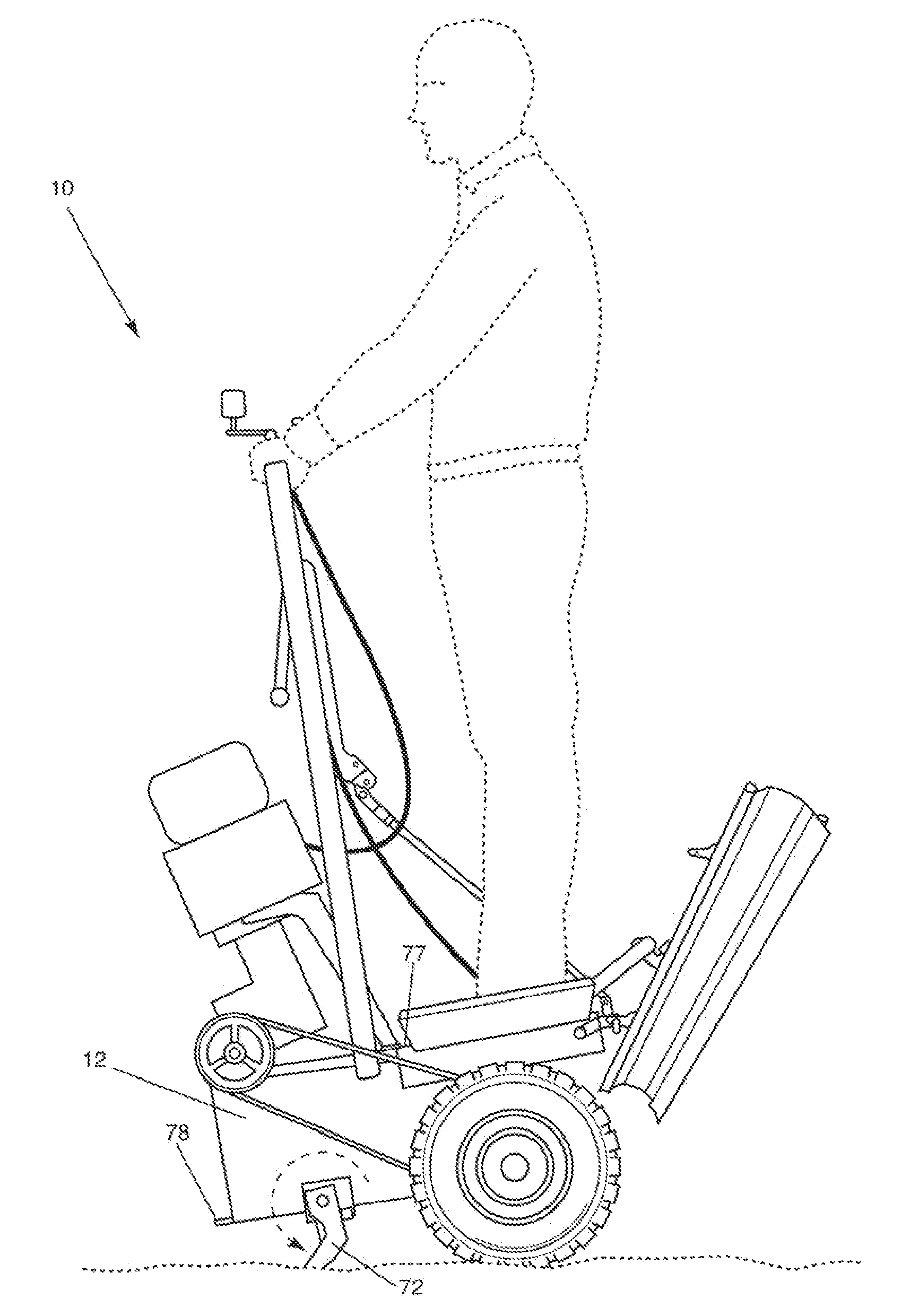
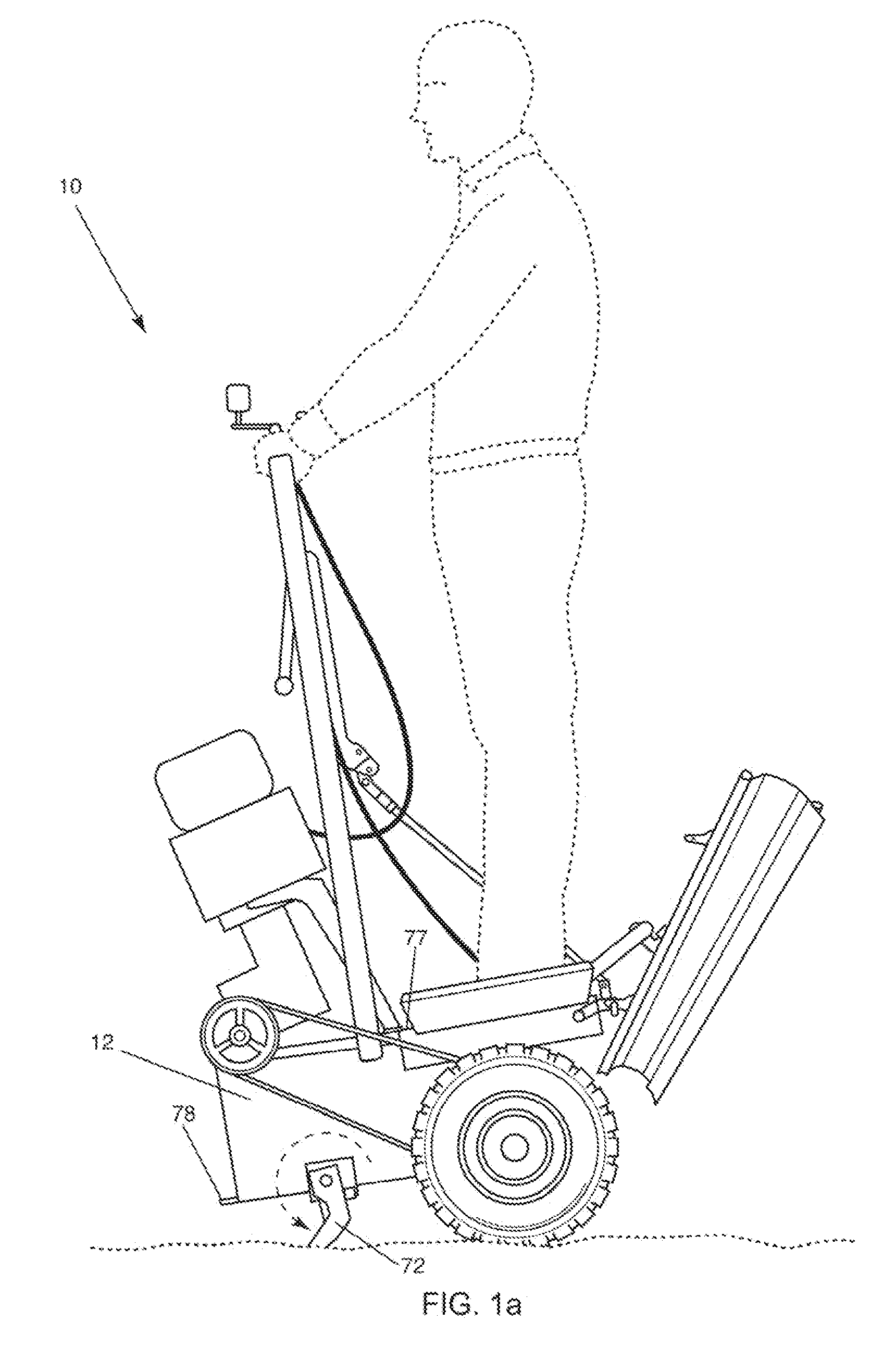
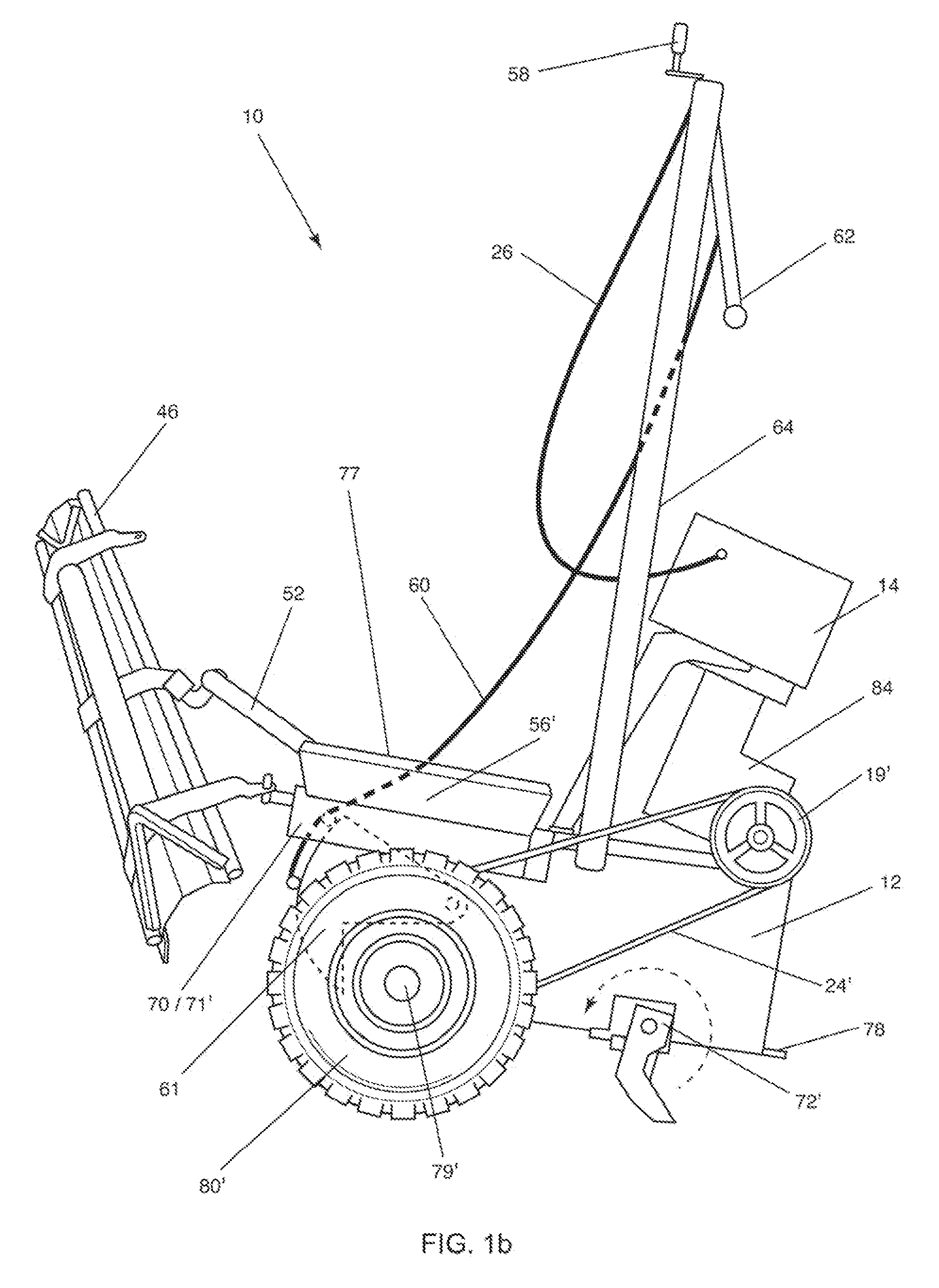
[0100]This example utilized the embodiment illustrated in FIGS. 1a-1i, comprising a single engine drive with drive sprocket clutches 19 and 19′ fitted with a snowplow attachment 96 on the front end as shown in FIG. 1i. Plow vertical member with swivel connection 95 was attached to bucket 12 by clamping around bucket blade 78, and horizontal plow member 97 was attached to bucket 12 with slotted hole fasteners at the bottom of the bucket near ripper stops 76 and 76′. Snow was plowed with the embodiment in an asphalt parking lot with a snow accumulation of approximately one foot with some packed snow, as evidenced by tracks from approximately three or four cars prior to starting the test. The size of the lot was 50 feet by 100 feet inside of the parking bumpers with a total of sixteen parking spaces in the lot with a twenty-foot wide roadway down the middle of the lot. Tire chains were also fitted on the embodiment used in this example.

[0101]The advantages of this embodiment of the pre...

example 3

[0106]An embodiment of the present invention comprising the dual engine type as shown in FIGS. 3a-3c was tested in conditions mimicking those typically found in the mountains in New Mexico. The dual engine embodiment cut a fire line in a forest firefighting situation. Flammable plant materials, degraded pine needles, leaves, and branches, were removed in a linear path, and the flammable materials were windrowed on the advancing fire side of the line. The majority of this work was performed using rear grading moldboard 46 with the dual engine embodiment in the walk behind position. Front bucket 12 was then used to cut more difficult dense growth areas with the dual engine embodiment in the mounted position.

[0107]Rear grading moldboard 46 initially cut the fire line while in the locked vertical angle position, where vertical angle turnbuckle 215 held the rear moldboard blade locked at a desired angle to the ground relative to axles 79 and 79′. Turnbuckle 215 was adjusted to force the ...


PUM


Abstract

Apparatus and method for material distribution, including a draw-bar to which is fixedly connected a bucket body. Wheels are attached to the drawbar on opposite sides of the bucket body between an open side and a gate thereof. A lower edge of the open side of the bucket body, which can receive material, is in the form of a cutting blade or teeth. The gate, which is disposed opposite from the open side, can be opened and closed. At least part of a top side of the bucket body forms a platform for an operator. At least one engine is provided and is drivingly connected to the wheels. A handlebar is connected to the bucket body, forward of the platform, for pivoting the bucket body about the wheels so that the cutting blade or teeth can be brought into or out of contact with a surface.

Description

[0001]The present invention claims priority from U.S. Provisional Patent Application No. 61 / 519,260, filed May 19, 2011 and entitled “Apparatus and Method for Improved Material Distribution”.BACKGROUND OF THE INVENTION[0002]The present invention relates to a compact and lightweight material moving apparatus and method of loading and moving material when performing construction, excavation, grading, landscaping, and other tasks.[0003]Various types of grading or material moving devices have been in existence for many years, for example historic horse-drawn blades to current large models for interstate highway construction. Disadvantages of machines currently known in the art include elevated cost, poor transportability, poor ability to work in confined areas, and width of gradable area being wider than desired. Machines currently used also use unacceptably elevated amounts of fuel and oil, and are not considered environmentally friendly.[0004]Further, power-assist devices have been in...

Claims


Application Information

Patent Timeline
Patent Type & Authority Applications(United States)
IPC IPC(8): E02F3/96E02F1/00E02F3/76E02F3/34E02F3/40
CPCE02F3/4075E02F3/46E02F3/56E02F3/769B62B2301/12E02F3/962E02F9/18E02F9/202E01H5/061E02F3/961
Inventor JONES, DAVID A.
Owner JONES DAVID A
Why Eureka
Try Eureka