System and method of power distribution control of an integrated circuit

a technology of power distribution control and integrated circuit, which is applied in the direction of electric variable regulation, process and machine control, instruments, etc., can solve the problems of high voltage regulators consuming a large amount of chip area, switches contributing to layout and routing complexity, and high voltage switches may be difficult to scale, so as to reduce the risk of switching, and limit the current leakage current

Active Publication Date: 2008-03-20
QUALCOMM INC
View PDF7 Cites 43 Cited by
  • Summary
  • Abstract
  • Description
  • Claims
  • Application Information

AI Technical Summary

Benefits of technology

The power manager integrated circuit has several advantages. Firstly, it can be made using a lower cost semiconductor manufacturing process and can be used with more expensive processes. Secondly, it reduces leakage current to a very low level, which means less current is wasted. Thirdly, it allows for a single regulator to provide power to multiple power domains within an integrated circuit device, reducing costs and complexity. Finally, it eliminates the need for leakage gating resources, which simplifies the design process.

Problems solved by technology

The patent text discusses the problem of reducing power consumption in portable electronic devices to improve battery life and increase available power budget for other features. Various power management techniques are used, such as generating multiple power supplies using power regulators or switching power supplies to disable power to embedded circuit structures when power is not needed. However, as devices become smaller, high voltage switches may be difficult to scale and contribute to layout and routing complexity. Therefore, there is a need for an improved power distribution system and method that reduces power loss.

Method used


Image

  • System and method of power distribution control of an integrated circuit
  • System and method of power distribution control of an integrated circuit
  • System and method of power distribution control of an integrated circuit

Examples


Embodiment Construction

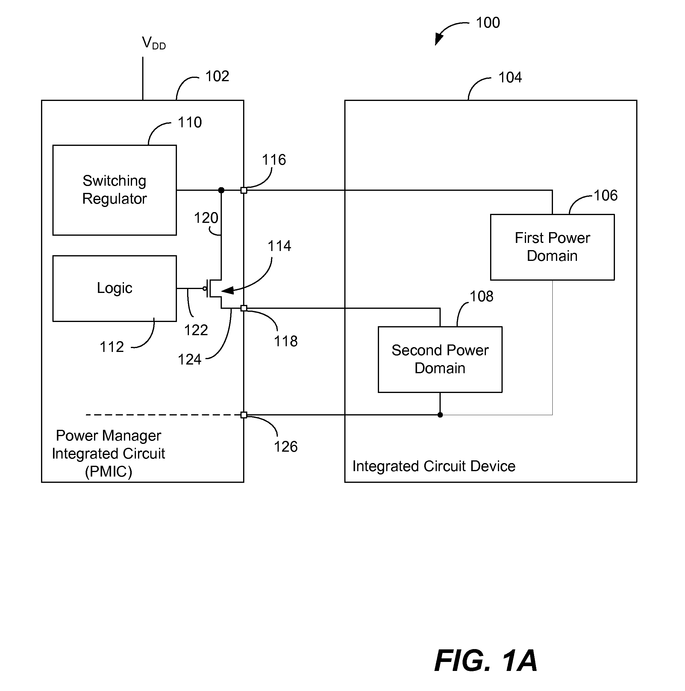
[0030]FIG. 1A is a block diagram of an illustrative embodiment of an electronic device 100 including a particular embodiment of a power manager integrated circuit (PMIC) 102 and an integrated circuit device 104. The integrated circuit device 104 may include multiple power domains, such as a first power domain 106 and a second power domain 108. The power manager integrated circuit 102 may include a switching regulator 110, logic 112, a transistor (switch) 114, a first pin 116 and a second pin 118. The switching regulator 110 is coupled to the first pin 116 and is coupled to the second pin 118 via the switch 114. The switch 114 may be a metal oxide semiconductor field effect transistor (MOSFET), a field effect transistor (FET), a bipolar junction transistor, or another circuit device that may be controlled by logic 112 to selectively enable and disable current flow to the second pin 118. In general, the switch 114 may be an n-channel MOSFET or a p-channel MOSFET device in the PMIC tec...


PUM


Abstract

A device is disclosed that includes a first pin to supply power to a first power domain of an integrated circuit, a second pin to supply power to a second power domain of the integrated circuit, a switching regulator and a controller. The switching regulator is coupled to the first pin to provide a first regulated power supply to the first power domain and is coupled to the second pin to provide a second regulated power supply to the second power domain. The controller is coupled to the first pin and to the second pin to selectively reduce current flow to at least the second pin during a low power event.

Description


Claims


Application Information

Patent Timeline
Owner QUALCOMM INC
Why Eureka
Try Eureka