Imaging apparatus, method, and program

Active Publication Date: 2008-03-20
FUJIFILM CORP
View PDF4 Cites 23 Cited by
  • Summary
  • Abstract
  • Description
  • Claims
  • Application Information

AI Technical Summary

Benefits of technology

[0007]The present invention has been developed in view of the circumstances described above, and it is an object of the presen

Problems solved by technology

Image corrections, however, require sophisticated techniques.
For example, it is difficult to correct an image taken when a person just blinked to an image of the person not blinking, or to correct an image of a person not smiling to an image of the person looking like smiling.
Further, when performing

Method used


Image

  • Imaging apparatus, method, and program
  • Imaging apparatus, method, and program
  • Imaging apparatus, method, and program

Examples


first embodiment

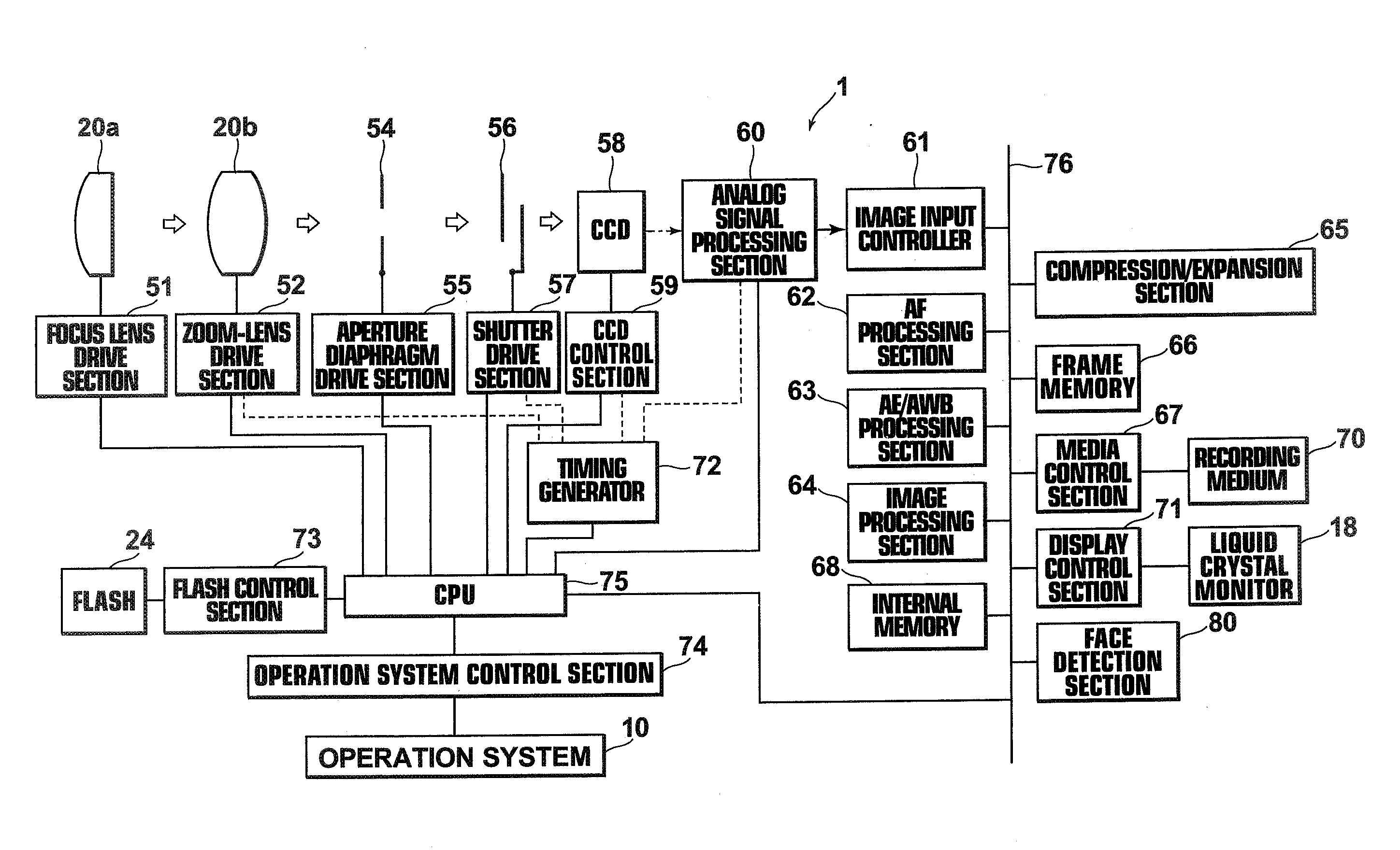
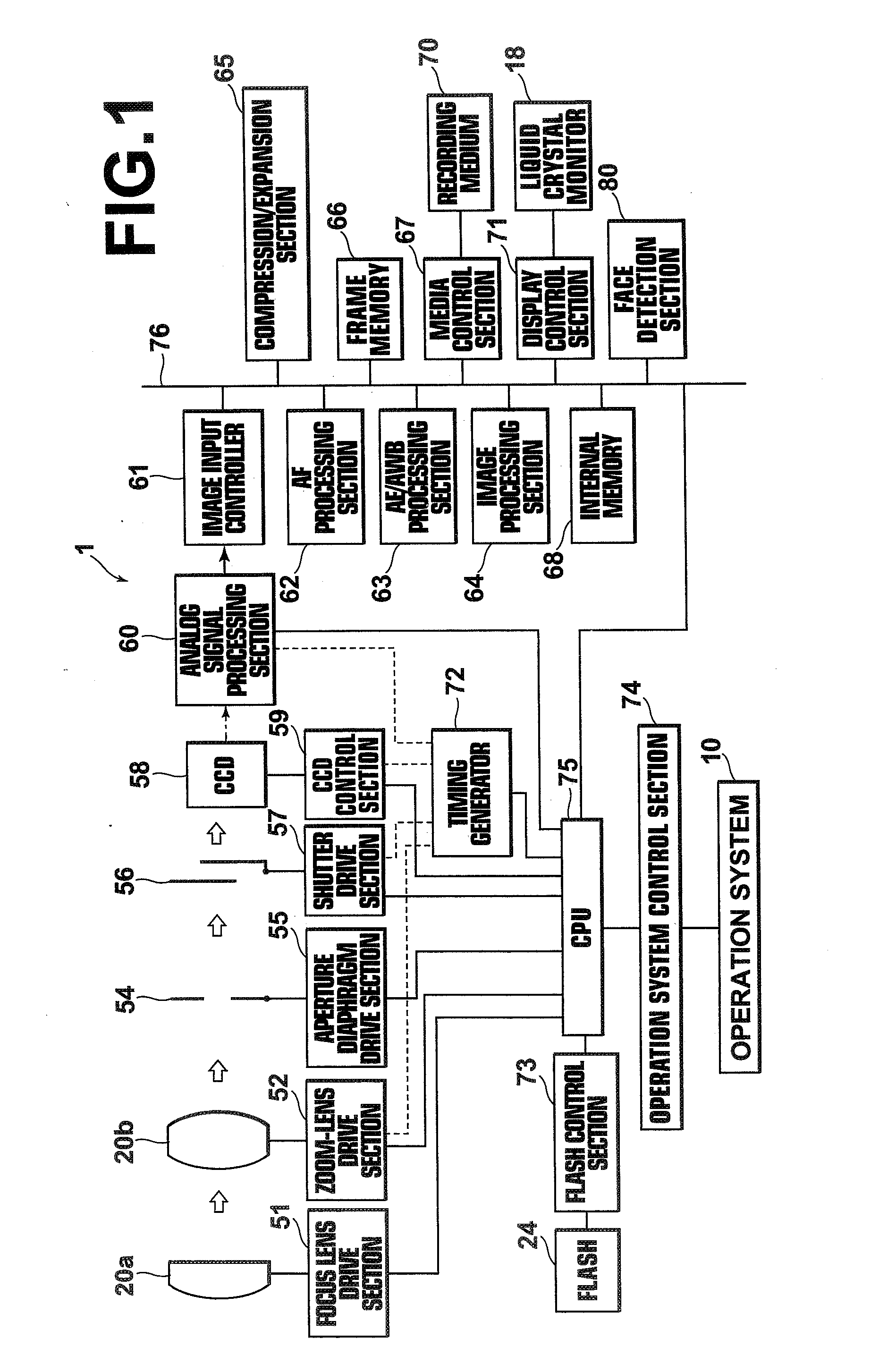
[0050]Hereinafter, exemplary embodiments of the present invention will be described with reference to the accompanying drawings. FIG. 1 is a schematic block diagram of a digital camera to which the imaging apparatus according to the present invention is applied, illustrating the construction thereof. The digital camera 1 shown in FIG. 1 converts image data obtained by imaging to an Exif image file, and records the image file on a recording medium 70 detachably attached to the main body.

[0051]The digital camera includes: an operation system 10 including an operation mode switch, a menu / OK button, a zoom-lever, an up-down arrow button, a back (return) button, a display switching button, a release button, a power switch, and the like; and an operation system control section 74, which is an interface section for transferring operational contents of these switches to a CUP 75.

[0052]In the present embodiment, a continuous imaging mode, in which imaging is performed continuously without th...

second embodiment

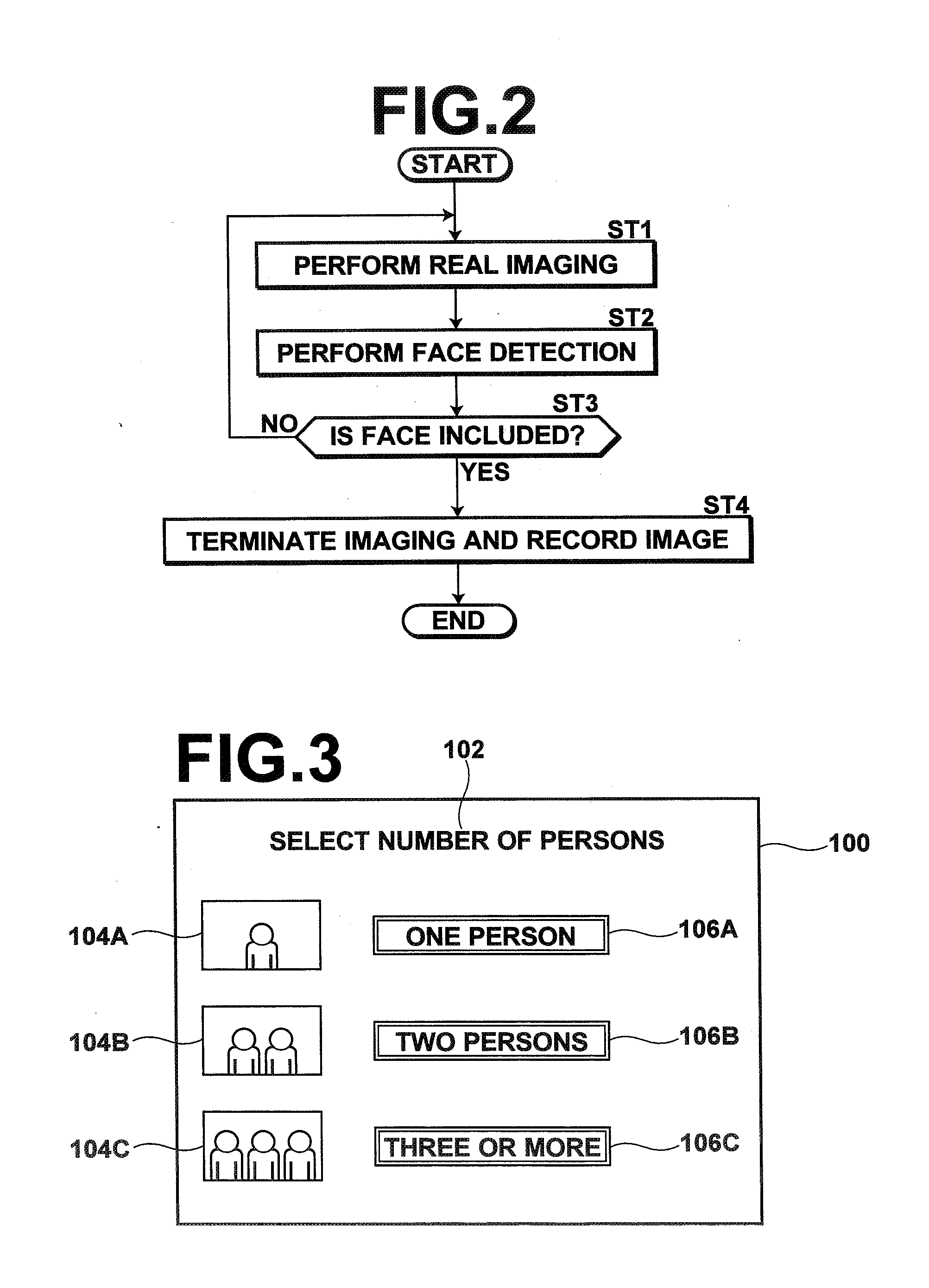
[0079]FIG. 4 is a flowchart illustrating a process performed in the When the operation mode of the digital camera 1 is set to continuous imaging mode, the process is initiated by the CUP 75 and real imaging is performed (step ST11). Then, the face detection section 80 performs face detection on a real image obtained through the real imaging (step ST12), and determines whether or not a face is included in the image (step ST13).

[0080]If step ST13 is negative, the process returns to step ST11, and the process sequence from step ST11 onward is repeated. If step ST13 is positive, a determination is made as to whether or not the number of detected faces corresponds to the specified number of persons (step ST14). If step ST14 is negative, the process returns to step ST11 and the process sequence from step ST11 onward is repeated. If step ST14 is positive, the imaging is terminated, and a real image determined to include the number of faces corresponding to the specified number of persons ...

third embodiment

[0085]FIG. 6 is a flowchart illustrating a process performed in the When the operation mode of the digital camera 1A is set to continuous imaging mode, the process is initiated by the CUP 75 and real imaging is performed (step ST21). Then, the face detection section 80 performs face detection on a real image obtained by the real imaging (step ST22), and determines whether or not a face is included in the image (step ST23).

[0086]If step ST23 is negative, the process returns to step ST21, and the process sequence from step ST21 onward is repeated. If step ST23 is positive, the shake detection section 82 performs shake detection (step ST24) and determines whether or not the amount of image shake is small (step ST25). If step ST25 is negative, the process returns to step ST21 and the process sequence from step ST21 onward is repeated. If step ST25 is positive, the imaging is terminated, and an image determined to have a less amount of image shake is recorded on the recording medium 70 ...


PUM


Abstract

An imaging apparatus capable of reliably obtaining and recording an image that satisfies a predetermined condition. When a continuous imaging mode is set through an operation system, an image is obtained through continuous imaging, and a determination is made as to whether or not the image obtained through the continuous imaging satisfies the predetermined condition. If the image is determined to satisfy the predetermined condition, the imaging is terminated and the image satisfying the predetermined condition is recorded.

Description

BACKGROUND OF THE INVENTION[0001]1. Field of the Invention[0002]The present invention relates to an imaging apparatus and method. The present invention also relates to a program for causing a computer to execute the imaging method.[0003]2. Description of the Related Art[0004]When imaging persons as subjects, image correction techniques used for correcting the person's faces to make them satisfactory are known. Image corrections, however, require sophisticated techniques. For example, it is difficult to correct an image taken when a person just blinked to an image of the person not blinking, or to correct an image of a person not smiling to an image of the person looking like smiling.[0005]For this reason, for example, an imaging apparatus that performs imaging when a predetermined condition, such as open eyes after closing for two seconds, not closed eyes, or the like, is satisfied by a subject is proposed as described, for example, in U.S. Pat. No. 7,248,300 and U.S. Patent Applica...

Claims


Application Information

Patent Timeline
IPC IPC(8): H04N5/225
CPCG03B17/00G03B17/38G03B2217/005H04N5/23251H04N5/23219H04N5/23222H04N5/23232G06K9/00228G06V40/161H04N23/64H04N23/611H04N23/951H04N23/681
Inventor TAMARU, MASAYASUGIMOTO, MASAHIKO
Owner FUJIFILM CORP
Why Eureka
Try Eureka