Flat-shaped battery

a battery and flat-shaped technology, applied in the field of flat-shaped batteries, can solve the problems of increasing the cost of the battery, the inability to obtain a contact resistance reduction, and the difficulty of uniform plating layer on the outer surface of the outer, so as to improve the smoothness of the surface of the positive electrode, improve the elasticity and insulation properties, and improve the effect of the battery capacity

Active Publication Date: 2011-03-29
MAXELL HLDG LTD
View PDF26 Cites 38 Cited by
  • Summary
  • Abstract
  • Description
  • Claims
  • Application Information

AI Technical Summary

Benefits of technology

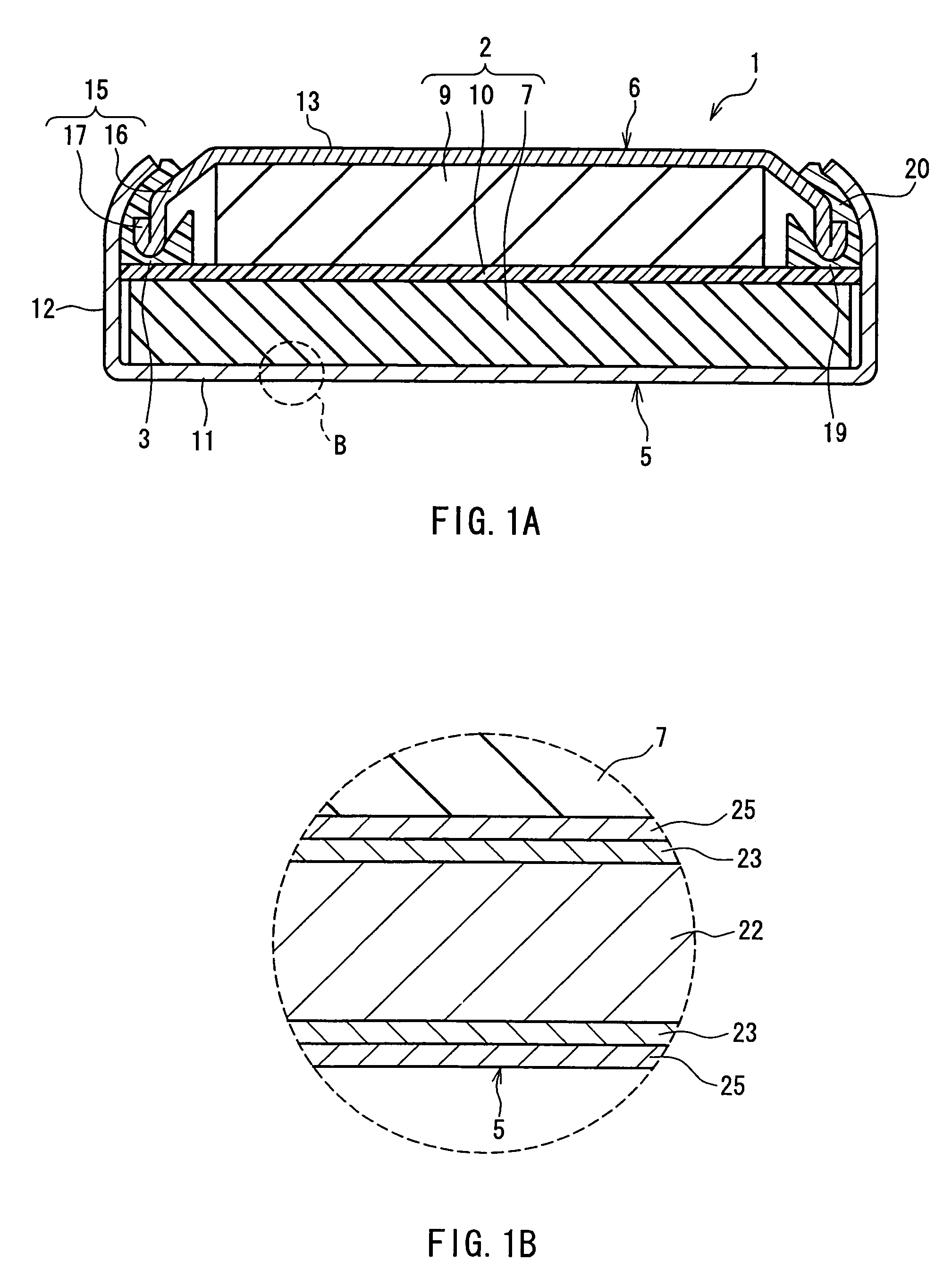
[0018]In the flat-shaped battery according to the present invention, the nickel plating layer 23 is present between the base 22 of the outer can 5 and the gold plating layer 25. Thus, the nickel plating layer 23 covers the recesses and projections on the surface of the base 22, thus smoothing out the surface of the outer can 5. Accordingly, even if the gold plating layer 25 is thin, the formation of pinholes can be prevented. Besides, since the thickness of the gold plating layer 25 can be reduced, the cost required for producing the battery can be reduced accordingly. Moreover, by providing the nickel plating layer 23 under the gold plating layer 25, it becomes possible to prevent the corrosion of the base 22 from being caused by any pinholes formed in the gold plating layer 25. Furthermore, the fact that the gold plating layer 25 is the outermost layer of the base 22 brings about further advantageous effects in that the value of the battery in terms of design can be improved by its glossy surface and that the contact resistance between the outer can 5 and a connection terminal of electronic equipment or the like can be decreased over a long time so that stable discharging characteristics can be reliably obtained. This is particularly advantageous in the case where the contact between the outer can 5 and the connection terminal is point contact. Furthermore, as compared with the case where the gold plating layer 25 is formed directly on the base 22, the adhesion of the gold plating layer 25 to the outer can 5 is improved by the nickel plating layer 23 intervening therebetween. Thus, the gold plating layer 25 can be prevented from being detached, for example, when the outer can 5 is subjected to press processing.
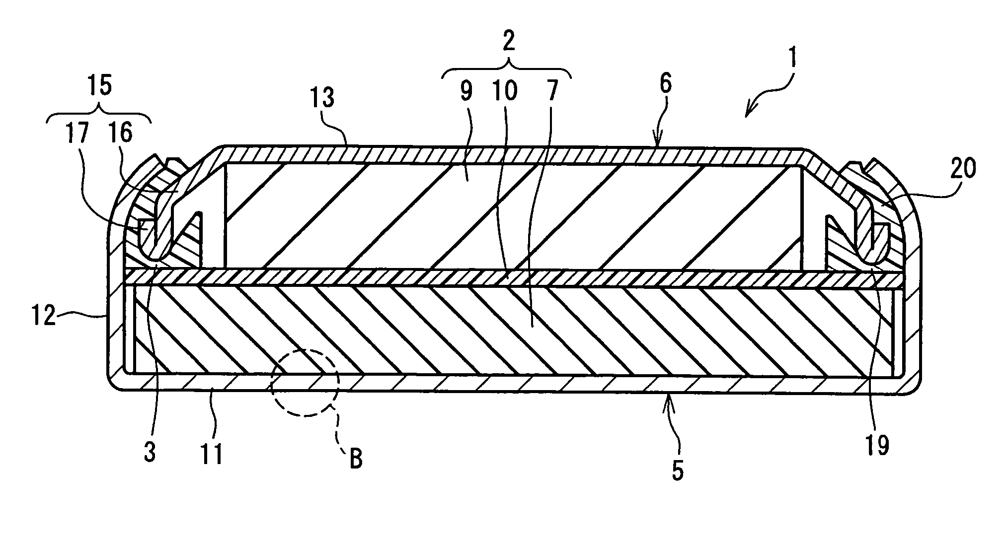
[0019]Hereinafter, one example of a flat-shaped battery according to the present invention configured so that an outer can 5 serves as a positive electrode and a sealing plate 6 serves as a negative electrode will be described with reference to the drawings. As shown in FIG. 1A, the flat-shaped battery 1 has a flat figure as a whole and includes an outer can (a positive electrode can) 5 for housing a power generation element 2 and a sealing plate (a negative electrode can) 6 that seals an opening provided at the upper end of the positive electrode can 5 by being fixed to the inner edge of the opening together with a gasket 3 by caulking. The power generation element 2 includes a disk-shaped positive electrode material 7, a disk-shaped negative electrode material 9, and a separator 10 provided between the positive electrode material 7 and the negative electrode material 9. The flat-shaped battery 1 is filled with an electrolyte solution. An electrolyte solution absorber (not shown) is laminated on the upper side of the separator 10.
[0020]The positive electrode material 7 is obtained by forming powders of a mixture containing silver oxide (Ag2O) as a positive active material, flake graphite as a conductive aid, etc. into a desired shape by pressing. The negative electrode material 9 is formed of zinc as a negative active material. The separator 10 is obtained by laminating a graft film on a cellophane film. As the graft film, it is possible to use a film obtained by graft-polymerizing methacrylic acid with cross-linked low-density polyethylene. The electrolyte solution is prepared by dissolving zinc oxide in a potassium hydroxide aqueous solution. The electrolyte solution absorber is formed of a mixture paper composed of vinylon and rayon.
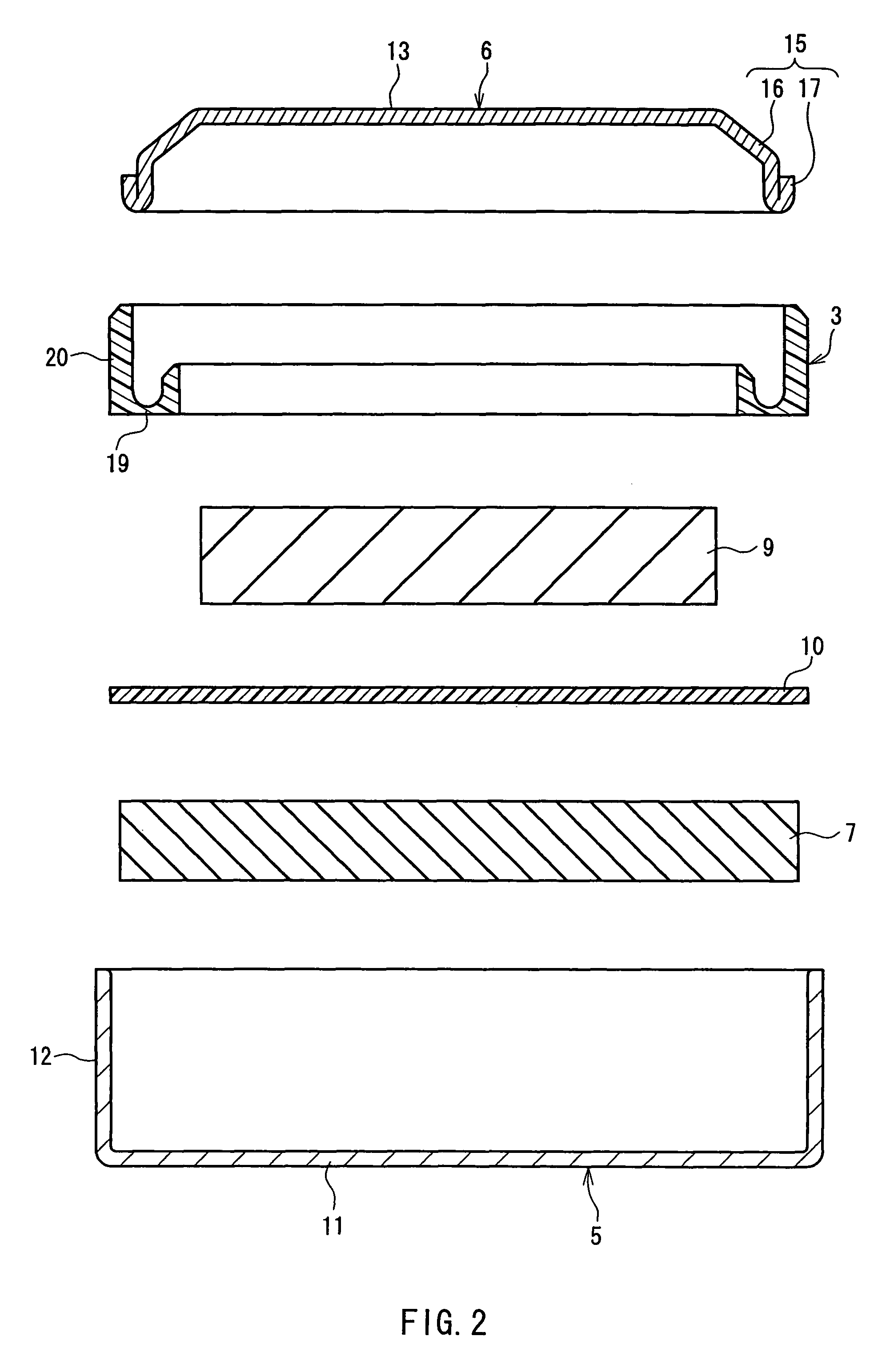
[0021]As shown in FIG. 2, before the assembly of the battery, the positive electrode can 5 has a shape like a deep round dish including a round bottom wall 11 and a peripheral side wall 12 that extends upward from the outer periphery of the bottom wall 11. The negative electrode can 6 has a shape like a shallow round dish including a round top wall 13 and a peripheral side wall 15 that extends downward from the outer periphery of the top wall 13. The peripheral side wall 15 of the negative electrode can 6 includes a diameter increasing portion 16 that extends obliquely downward from the outer periphery of the top wall 13 and a sealing portion 17 provided continuously at the lower end of the diameter increasing portion 16 and folded so as to extend upward.
[0022]The gasket 3 is made of a polyamide-based resin with excellent elasticity and insulation properties, such as Nylon 66, and is formed into a ring shape by injection molding. The gasket 3 is disposed on the upper side of the positive electrode material 7 via the separator 10. The gasket 3 includes a ring-shaped base portion 19 and an outer cylinder wall 20 that projects upward from an outer edge portion of the base portion 19 and is to be held between the peripheral side wall 12 of the positive electrode can 5 and the peripheral side wall 15 of the negative electrode can 6. The negative electrode can 6 is formed of a clad material with a three-layer structure composed of a copper layer, a steel layer, and a nickel layer, and the outer side of the copper layer is plated with tin. Note here that the copper layer-side of the negative electrode can 6 would be an inner side of the battery.
[0023]As shown in FIG. 1B, the positive electrode can 5 is configured so that nickel plating layers 23 are formed respectively on both surfaces of a base 22 that is formed of iron alone or an iron alloy such as stainless steel and gold plating layers 25 are formed on the outer side of the respective nickel plating layers 23. The thickness of the base 22 of the positive electrode can 5 preferably is in the range from 50 to 300 μm. When the thickness of the base 22 is smaller than 50 μm, the base 22 has insufficient strength required for a base such that it can be deformed easily. On the other hand, a thickness of the base 22 greater than 300 μm is not preferable because, although the base has sufficient strength, the battery capacity relative to the battery volume becomes small due to the increase in the thickness of the base. The nickel plating layers 23 of the positive electrode can 5 can be formed of nickel alone or be a nickel-containing layer such as a nickel alloy, such as an alloy of nickel and chromium or the like. The specific composition of the nickel plating layer is not critical. Each of the nickel plating layers 23 can be formed by performing electroplating, hot-dip plating, vacuum plating, or the like with respect to the base 22.

Problems solved by technology

Thus, when the thickness of the gold plating layer is small, it is difficult to form the plating layer uniformly on the outer surface of the outer can because the recesses and projections on the base exist on the surface of the outer can.
In the case where the pinholes are formed as described above, a decrease in the contact resistance cannot be obtained when the contact portion between the outer can and electronic equipment is a portion where the pinhole is present.
However, since the thickness of the gold plating layer needs to be greater than a vertical interval (an interval between the crest and the trough) of the recesses and projections, the cost of the battery increases considerably.
Moreover, gold is soft and achieves only low adhesion to a stainless steel plate.
Thus, when the gold plating layer is formed so as to have a thickness that can cover the vertical interval of the recesses and projections as described above, the plating layer formed nonuniformly is liable to be damaged so that, at the time of a caulking process or the like during the production of the battery, the gold plating layer may adhere to the inner surface of a die to be detached easily.
This brings about another problem that the thus-formed gold plating layer may be detached from the outer can.

Method used


Image

  • Flat-shaped battery
  • Flat-shaped battery
  • Flat-shaped battery

Examples


example 1

[0035]A flat-shaped battery having the configuration as shown in FIG. 1A was produced in the following manner.

[0036] A stainless steel plate (SUS 430, bright annealed finish) having a surface roughness Ra of 5.5 and a thickness of 150 μm was used as the base 22.

[0037] The surface roughness Ra of the outer surface of the nickel plating layer 23 was 1.3, and the thickness of the nickel plating layer 23 was 5 μm.

[0038] The gold plating layer 25 had a thickness of 0.1 μm.

[0039]Except for the above, the configuration of the flat-shaped battery according to Example 1 is the same as that of the above-described flat-shaped battery shown in FIG. 1A, and description thereof thus has been omitted.

example 2

[0040]A flat-shaped battery was produced in the same manner as in Example 1, except that the thickness of the gold plating layer 25 was 0.3 μm.

example 3

[0041]A flat-shaped battery was produced in the same manner as in Example 1, except that the thickness of the gold plating layer 25 was 0.5 μm.


PUM

PropertyMeasurementUnit
thicknessaaaaaaaaaa
thicknessaaaaaaaaaa
thicknessaaaaaaaaaa

Abstract

A flat-shaped battery according to the present invention includes: an outer can having an opening at its upper end; a gasket disposed at an inner edge of the opening; and a sealing plate that seals the opening together with the gasket. In this flat-shaped battery, the outer can houses a power generation element, the sealing plate is fixed to the inner edge of the opening of the outer can via the gasket by caulking, a nickel or nickel-containing plating layer having a thickness in a range from 1 to 10 μm is formed on an outer surface of a base composing the outer can, and a gold or gold-containing plating layer is formed on an outer surface of the nickel or nickel-containing plating layer.

Description

BACKGROUND OF THE INVENTION[0001]1. Field of the Invention[0002]The present invention relates to a flat-shaped battery that is formed in a flat shape such as a coin shape or a button shape as a whole and is to be used in electronic equipment such as a wristwatch.[0003]2. Description of Related Art[0004]JP 50(1975)-12533 A and JP 59(1984)-166359 U disclose a flat-shaped battery configured so that a positive electrode can for housing a power generation element is used as an outer can and a sealing plate that seals an opening provided at the upper end of the positive electrode can by being fixed to the inner edge of the opening together with a gasket by caulking is used as a negative electrode can. In JP 50(1975)-12533 A and JP 59(1984)-166359 U, a gold plating layer is formed on the outer surface of a stainless steel as a base composing the negative electrode can.[0005]When the outer surface of a stainless steel base is covered with the gold plating layer as disclosed in JP 50 (1975)-...

Claims


Application Information

Patent Timeline
Patent Type & Authority Patents(United States)
IPC IPC(8): H01M2/00H01M2/08H01M50/119H01M50/128H01M50/131H01M50/133
CPCH01M2/0222H01M2/0262H01M2/027H01M2/0275H01M2/0287H01M6/12H01L2924/0002H01L2924/00H01M50/109H01M50/545H01M50/124H01M50/133H01M50/131H01M50/128H01M50/119
Inventor KIMURA, TAKASHISANO, KENICHI
Owner MAXELL HLDG LTD
Why Eureka
Try Eureka