
Pumping System

a technology of pumping system and pumping chamber, which is applied in the direction of liquid fuel engine, rotary piston engine, rotary or oscillating piston engine, etc., can solve the problems that the existing control system of this type has not been entirely satisfactory, and achieves the effect of improving the control system

Active Publication Date: 2008-03-20
PIERBURG PUMP TECH ITAL
View PDF2 Cites 44 Cited by
  • Summary
  • Abstract
  • Description
  • Claims
  • Application Information

AI Technical Summary

Benefits of technology

[0008]It is therefore an object of the present invention to provide a straightforward hydraulic control for controlling a pump, e.g. a variable-displacement vane pump, as a function of delivery pressure and another engine operating parameter, such as oil temperature.

Problems solved by technology

Existing control systems of this type, however, have not proved altogether satisfactory, by subjecting the ring to severe forces that are difficult to control.

Method used


Image

  • Pumping System
  • Pumping System
  • Pumping System

Examples


Embodiment Construction

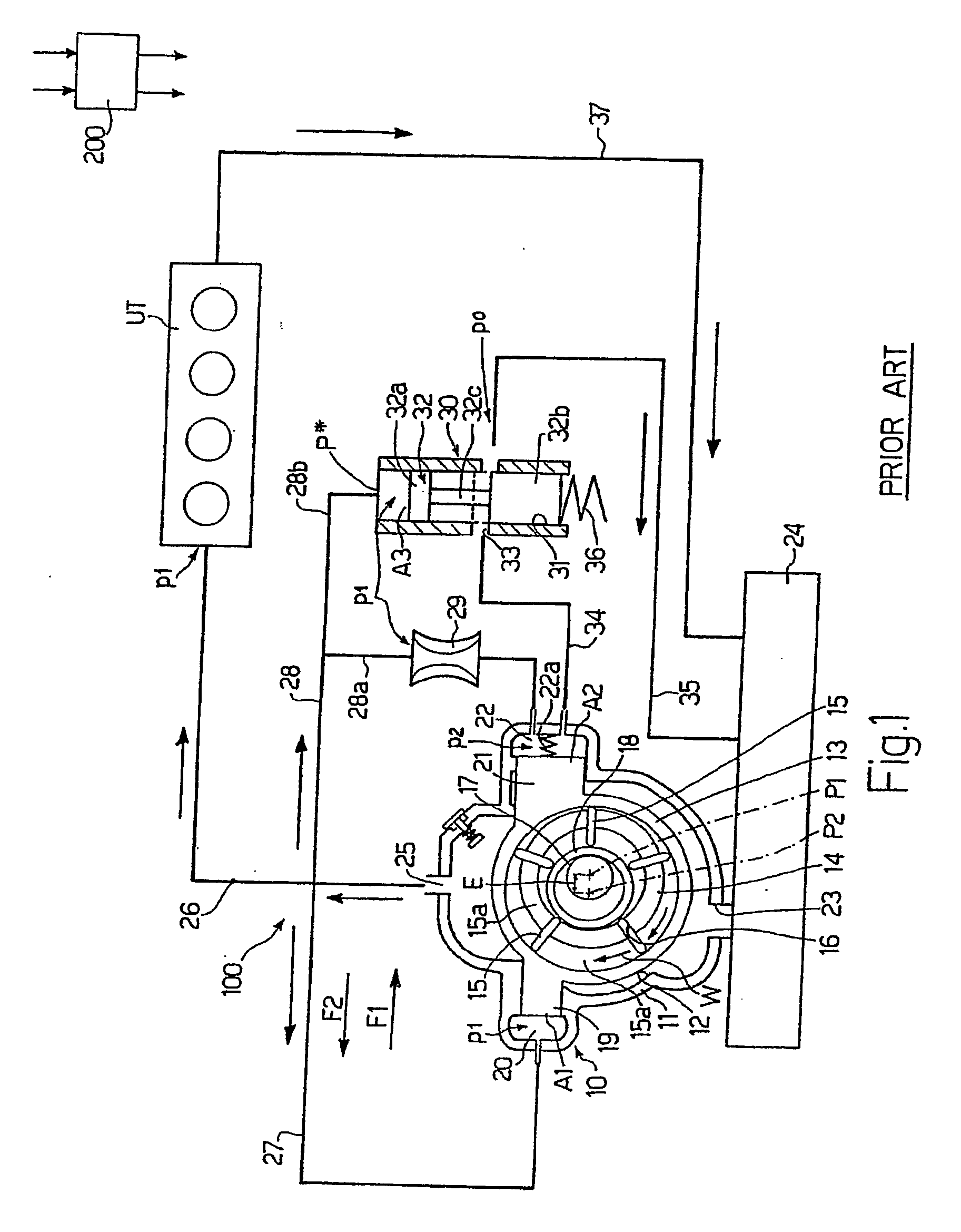
[0017]For a clear understanding of the present invention, reference will first be made to the known system in FIG. 1, which is the object of the Applicant's International Application PCT / EP2004 / 052140, and on which the system according to the present invention is based.

[0018]Number 10 in FIG. 1 indicates a variable-delivery vane pump forming part of a pumping system 100 which is the object of the Applicant's Italian Patent Application BO2003A000528.

[0019]Pump 10 comprises, in known manner, a main body 11 having a cavity 12, in which a ring 13 translates as explained in detail later on.

[0020]Ring 13 houses a rotor 14 having vanes 15, which are movable radially inside respective radial slots 16 formed in rotor 14, which in turn is rotated in the direction indicated by arrow W (see below).

[0021]Main body 11 is closed by a cover not shown in the accompanying drawings.

[0022]In known manner, rotor 14 houses a shaft 17 connected mechanically to rotor 14; and a floating ring 18 surrounding ...


PUM


Abstract

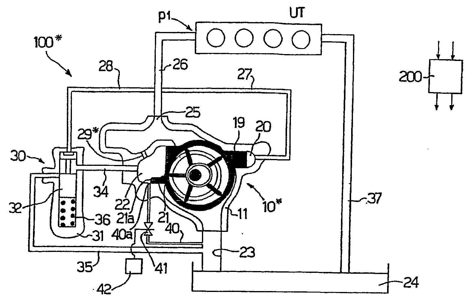
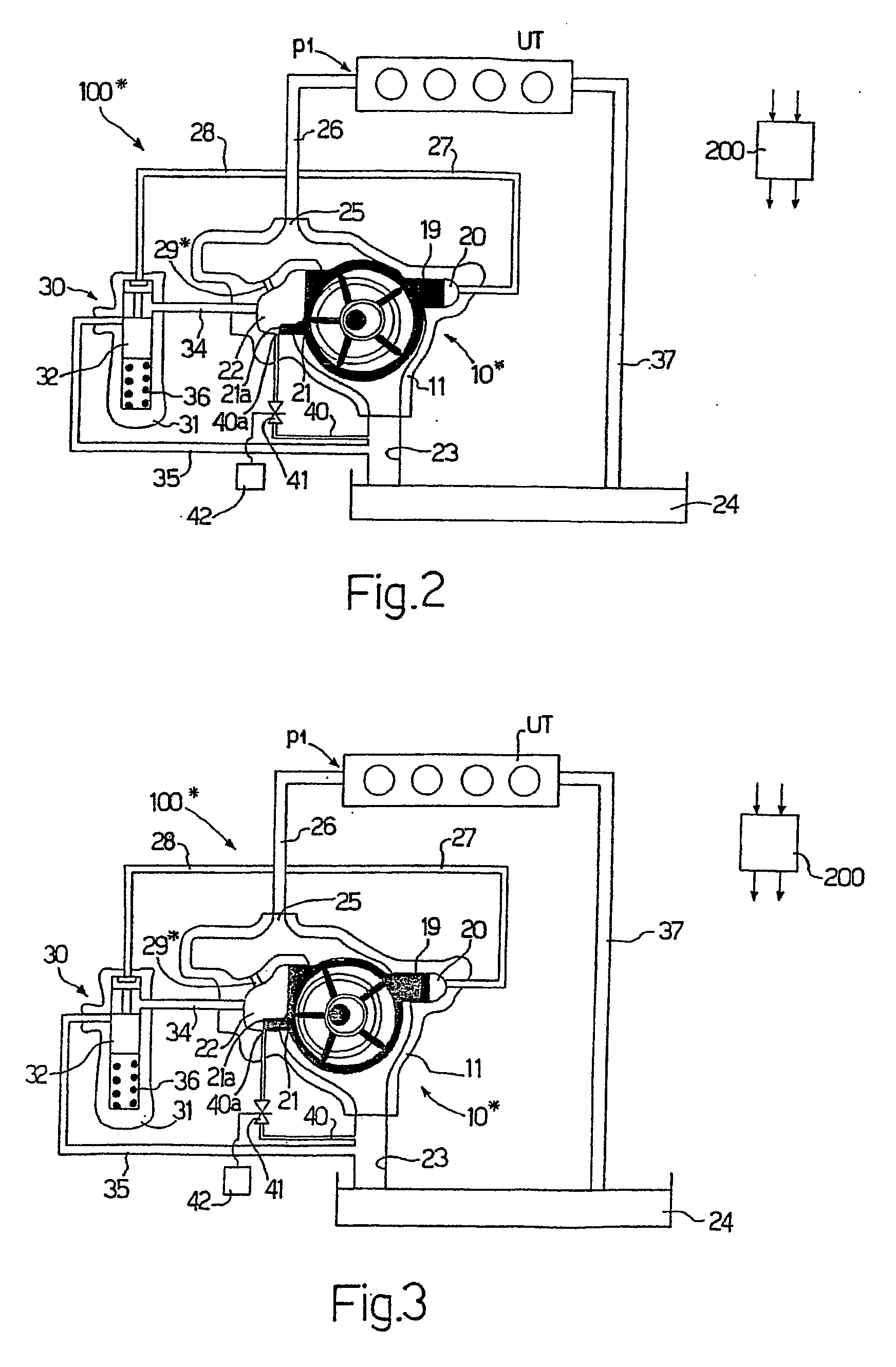
A pumping system (100*) having a pump (10*), such as a variable-displacement vane pump (10*) or a gear pump. The pump (10*) in turn has hydraulic pressure-control dissipating devices (29, 30) for imparting to the oil in a first control chamber (22) a pressure (p2) lower than the pressure of a second chamber (20). The system (100*) is characterized in that the first control chamber (22) of the pump (10*) has a channel (40) connecting the first control chamber to an oil inlet (23). And the channel (40) has an opening / closing device (41) controlled selectively by an engine operating parameter, such as oil temperature.

Description

TECHNICAL FIELD[0001]The present invention relates to a pumping system. More specifically, the present invention relates to control of a variable-displacement vane pump or gear pump.[0002]Though reference is made in the following description to a variable-displacement vane pump, the teachings of the present invention may also be applied to advantage to a gear pump (not shown).BACKGROUND ART[0003]As is known, vane pumps of the above type are currently used for pumping various fluids, such as lubricating oil in an internal combustion engine.[0004]In the present invention, operation of the pump is controlled by delivery pressure and a further parameter, e.g. oil temperature.[0005]Pumping systems are known, in fact, which are controlled not only by the delivery pressure of the pump but also by oil temperature.[0006]Two such control systems are described in U.S. Pat. No. 5,800,131 and FR-2 825 419, in which a member sensitive to variations in oil temperature acts directly on the pump rin...

Claims


Application Information

Patent Timeline
Patent Type & Authority Applications(United States)
IPC IPC(8): F04B49/00F04C2/344F04C14/22
CPCF04C2/3442F04C2270/19F04C14/223
Inventor ARMENIO, GIACOMOCELATA, BERNARDO
Owner PIERBURG PUMP TECH ITAL
Learn More