Radio-over-fiber (RoF) optical fiber cable system with transponder diversity and RoF wireless picocellular system using same

a technology of optical fiber cable and transponder diversity, applied in the field of wireless communication systems, can solve the problems of affecting the operation of the wireless system/network, the difficulty of scaling, and the possibility of one or more transponders being obstructed by a portion of the building structure,

Inactive Publication Date: 2008-03-20
CORNING OPTICAL COMM LLC
View PDF99 Cites 110 Cited by
  • Summary
  • Abstract
  • Description
  • Claims
  • Application Information

AI Technical Summary

Benefits of technology

[0010]One aspect of the invention is a radio-over-fiber (RoF) optical fiber cable system with transponder diversity for a RoF wireless picocellular system. The system includes at least one optical fiber cable and two or more transponders optically supported by the at least one optical fiber cable. The two or more transponders are arranged to form one or more groups of two or more proximately located transponders. The transponders in a given transponder group are adapted to form corresponding two or more substantially co-located picocells. The system also includes a diversity combiner optically coupled to each transponder. The diversity combiner is adapted to determine respective signal strengths from each transponder in each transponder group to ensure the transponder with the greatest signal strength in a given transponder group is used to form the picocell for the given group.

Problems solved by technology

This makes the wireless system / network relatively complex and difficult to scale, particularly when many picocells need to cover a large region.
Further, the digital information processing performed at the access point devices requires that these devices be activated and controlled by the head-end controller, which further complicates the distribution and use of numerous access point devices to produce a large picocellular coverage area.
A problem with such cable installation is the chance of one or more transponders being obstructed by a portion of the building structure, such as metallic framework of a drop-down ceiling.
The effect of such an obstruction degrades the radiation characteristics of the antenna, which reduces the ability of the picocell to properly function.
Another problem is the multi-path (fading) nature of signal propagation in indoor wireless environments.

Method used


Image

  • Radio-over-fiber (RoF) optical fiber cable system with transponder diversity and RoF wireless picocellular system using same
  • Radio-over-fiber (RoF) optical fiber cable system with transponder diversity and RoF wireless picocellular system using same
  • Radio-over-fiber (RoF) optical fiber cable system with transponder diversity and RoF wireless picocellular system using same

Examples


Embodiment Construction

[0040]Reference is now made in detail to the present preferred embodiments of the invention, examples of which are illustrated in the accompanying drawings. Whenever possible, the same or analogous reference numbers are used throughout the drawings to refer to the same or like parts.

Generalized Optical-Fiber-Based Wireless System

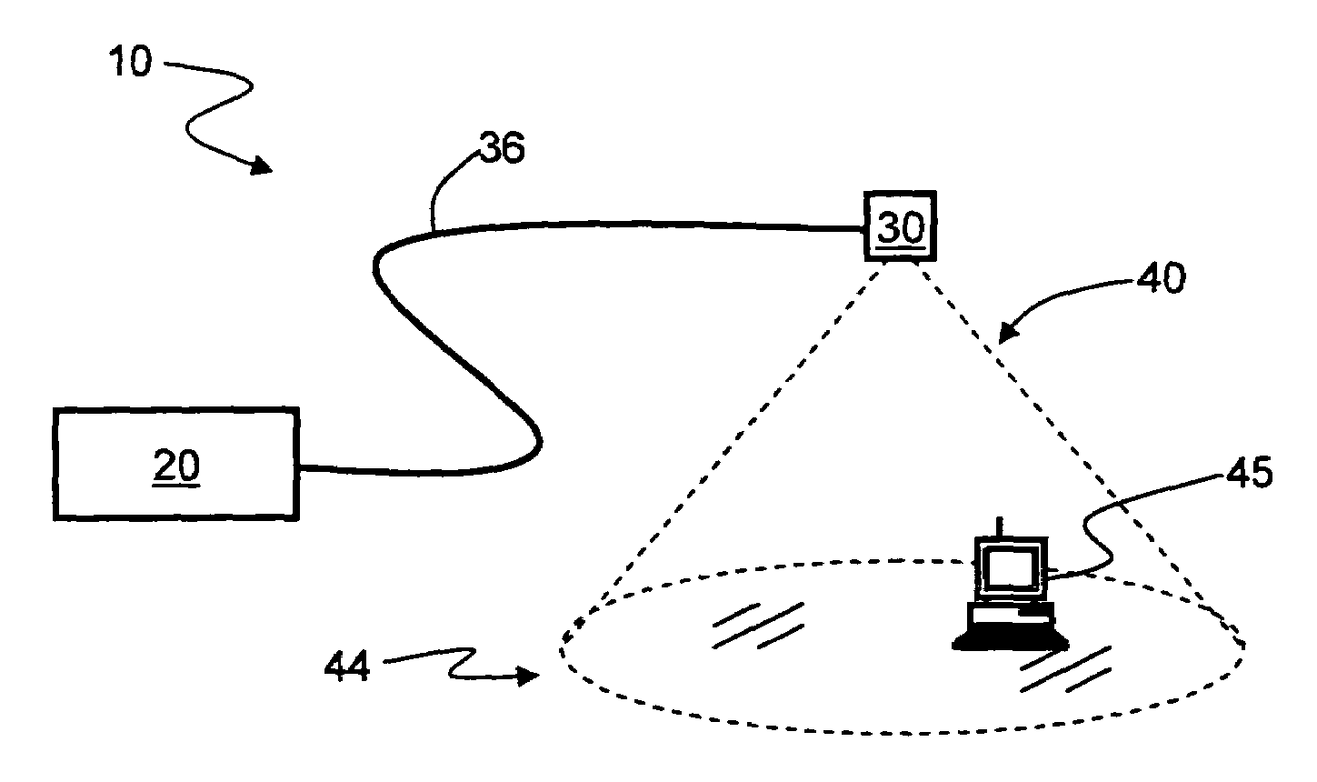
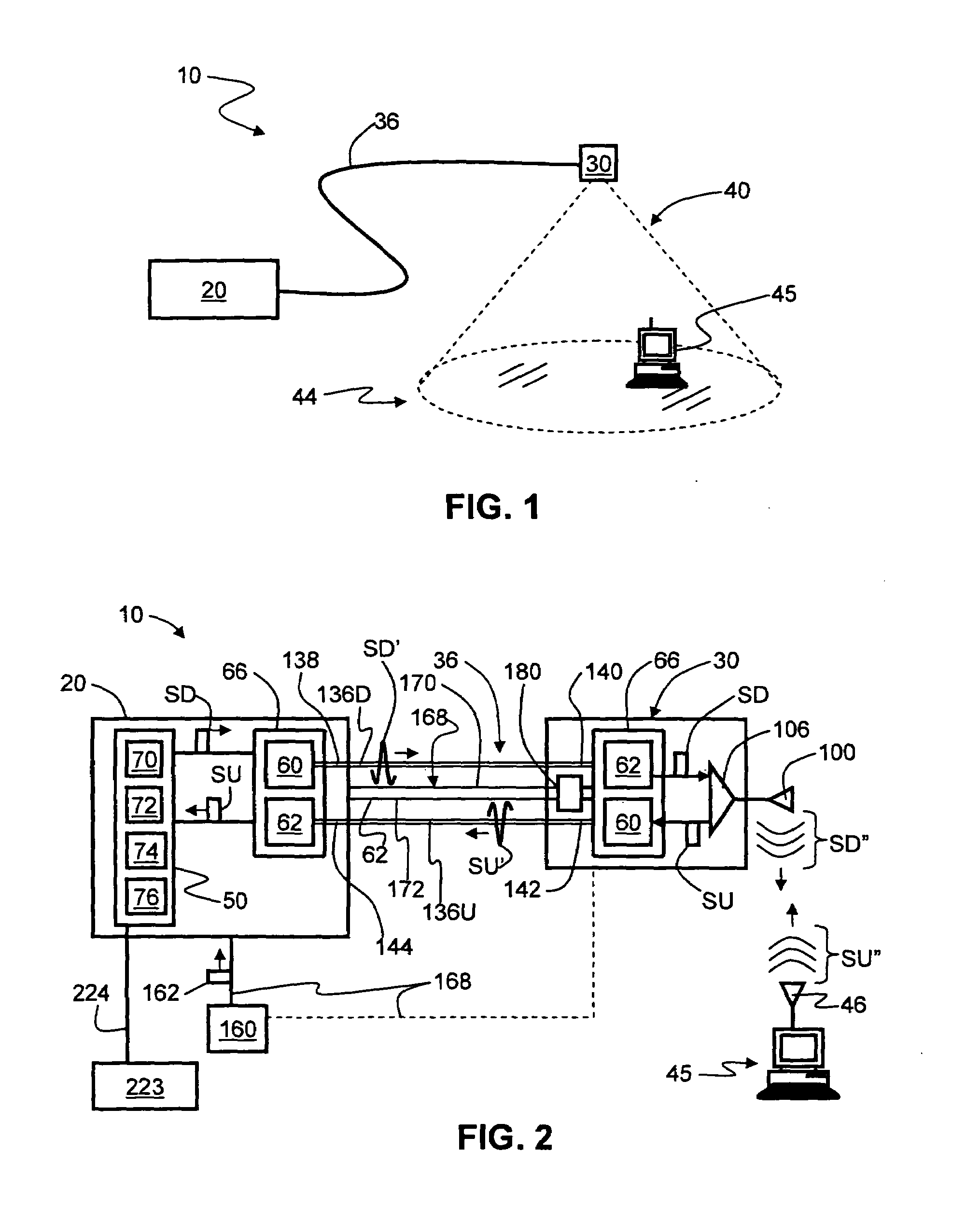
[0041]FIG. 1 is a schematic diagram of a generalized embodiment of an optical-fiber-based wireless picocellular system 10 according to the present invention. System 10 includes a head-end unit 20, one or more transponder units (“transponder”) 30 and an optical fiber RF communication link 36 that optically couples the head-end unit to the transponder. As discussed in detail below, system 10 has a picocell 40 substantially centered about transponder 30. The one or more transponders 30 form a picocellular coverage area 44. Head-end unit 20 is adapted to perform or to facilitate any one of a number of RF-over-fiber applications, such as radio-frequency identific...


PUM


Abstract

A radio-over-fiber (RoF) optical fiber cable system with transponder diversity for a RoF wireless picocellular system that includes at least one optical fiber cable. The at least one optical fiber cable supports one or more groups of two or more transponders, wherein the transponders in a given group are arranged to form substantially co-located picocells. The transponders in each transponder group may also have one of two orthogonal antenna polarizations. A diversity combiner optically coupled to each transponder determines respective signal strengths from each transponder in each transponder group. The transponder with the greatest signal strength in a given transponder group is selected to form the picocell for the given group. This allows for the optical fiber cable system to adjust to changes in the signal strength of each picocell, such as caused by a transponder obstruction or failure.

Description

BACKGROUND OF THE INVENTION[0001]1. Field of the Invention[0002]The present invention relates generally to wireless communication systems, and in particular relates to centralized optical-fiber-based wireless systems and methods employing radio-frequency (RF) transmission over optical fiber.[0003]2. Technical Background[0004]Wireless communication is rapidly growing, with ever-increasing demands for high-speed mobile data communication. As an example, so-called “wireless fidelity” or “WiFi” systems and wireless local area networks (WLANs) are being deployed in many different types of areas (coffee shops, airports, libraries, etc.). Wireless communication systems communicate with wireless devices called “clients,” which must reside within the wireless range or “cell coverage area” in order to communicate with the access point device.[0005]One approach to deploying a wireless communication system involves the use of “picocells,” which are radio-frequency (RF) coverage areas having a r...

Claims


Application Information

Patent Timeline
Patent Type & Authority Applications(United States)
IPC IPC(8): H04B7/00H04Q7/20
CPCH04B10/25756H04B10/25759
Inventor GEORGE, JACOBSAUER, MICHAEL
Owner CORNING OPTICAL COMM LLC
Why Eureka
Try Eureka