
Initiating medical system communications

a technology of medical system and communication, applied in the field of medical system, can solve problems such as significant consumption of power

Inactive Publication Date: 2008-03-20
MEDTRONIC INC
View PDF16 Cites 1194 Cited by
  • Summary
  • Abstract
  • Description
  • Claims
  • Application Information

AI Technical Summary

Problems solved by technology

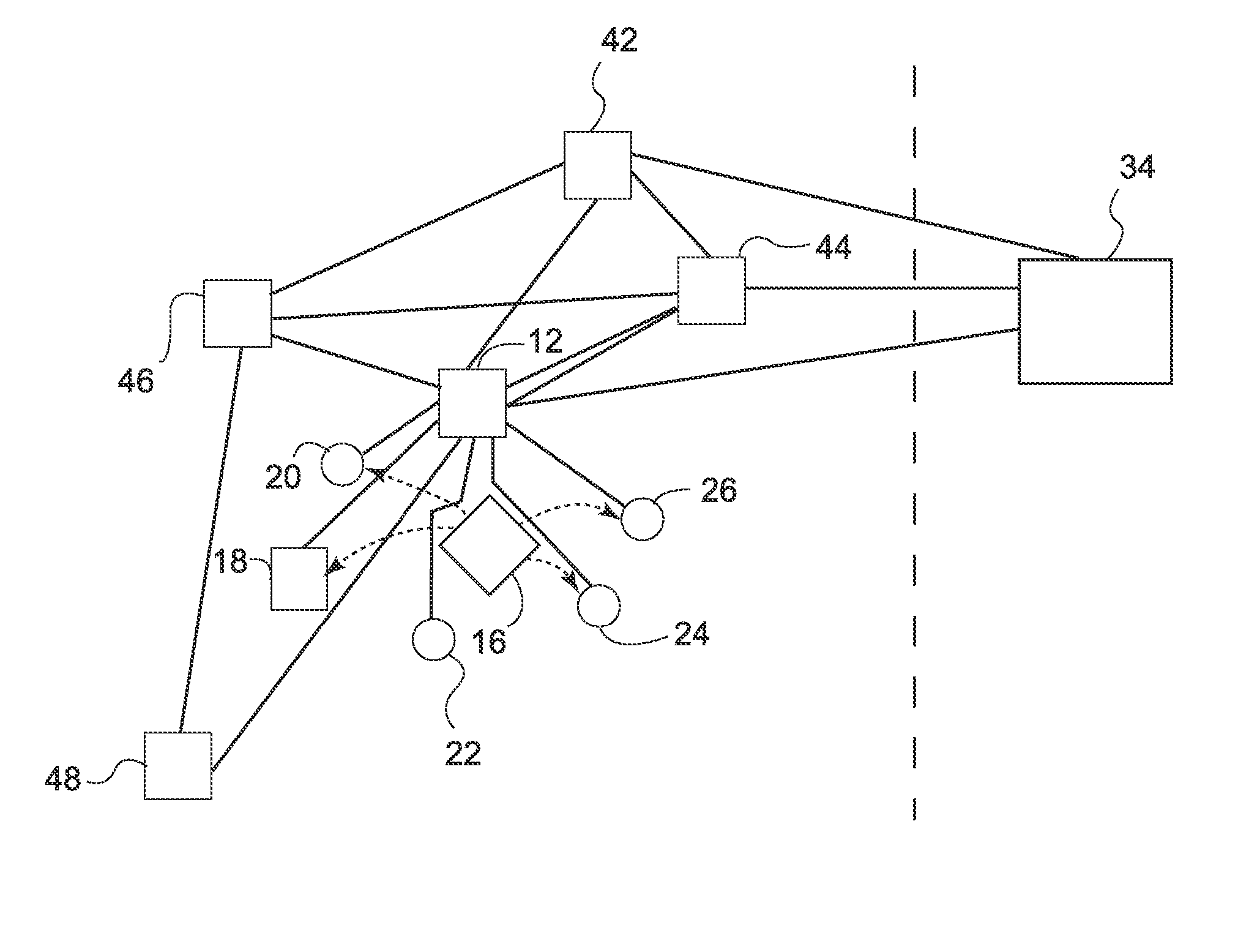
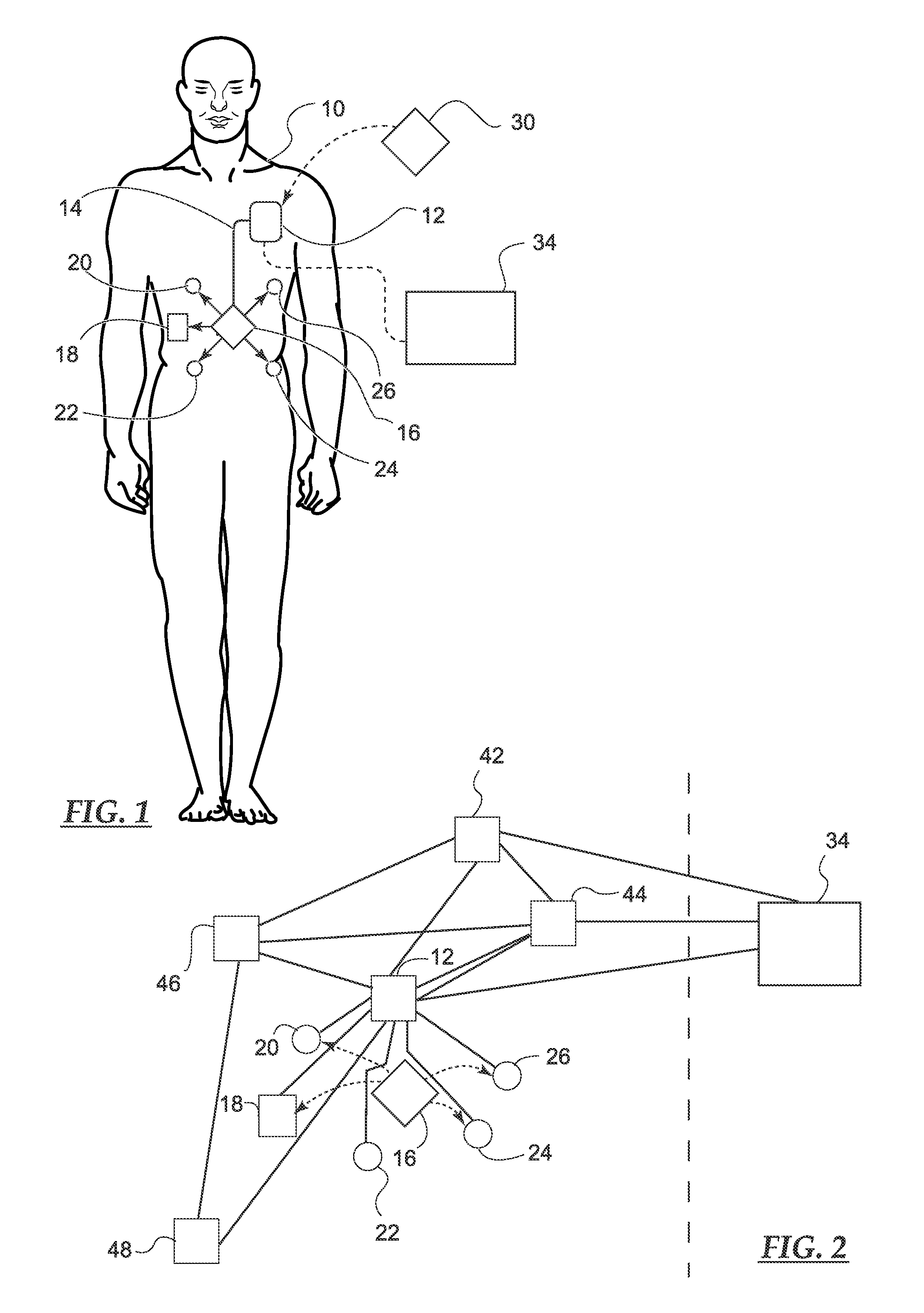
However, if communications components in each device of the system were to remain active at all times, ready to receive communications from one another, a significant amount of power would be consumed.

Method used


Image

  • Initiating medical system communications
  • Initiating medical system communications
  • Initiating medical system communications

Examples


Embodiment Construction

[0012] The following detailed description is exemplary in nature and is not intended to limit the scope, applicability, or configuration of the invention in any way. Rather, the following description provides practical illustrations for implementing exemplary embodiments of the present invention. Those skilled in the art will recognize that many of the examples provided have suitable alternatives that can be utilized. As used herein, the term “module” refers to an application specific integrated circuit (ASIC), an electronic circuit, a processor (shared, dedicated, or group) and memory that execute one or more software or firmware programs, a combinational logic circuit, or other suitable components that provide the described functionality.

[0013] The present invention is directed to an ultra-low power, local communications network for use with a medical device system including one or more implanted devices. As used herein, the term “constellation” of devices refers to implantable m...


PUM


Abstract

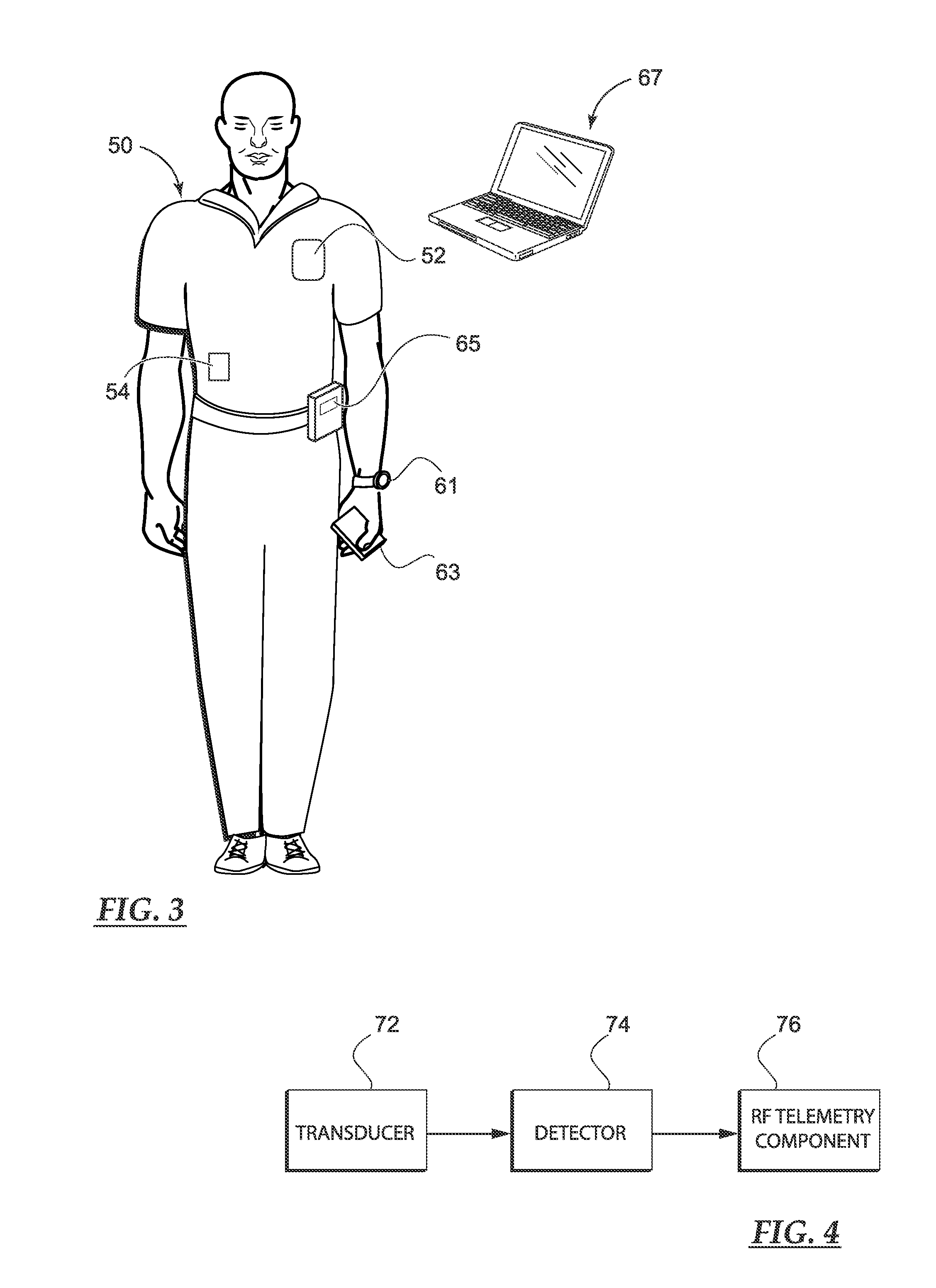
A medical system includes a body-contacting signal source adapted to transmit an oscillatory signal though a body to a transducer of a device implanted therein. A detector that is coupled to the transducer, upon detection of a response of the transducer to the signal, activates a radio-frequency (RF) telemetry component of the device.

Description

CROSS-REFERENCE TO RELATED APPLICATION(S) [0001] This application claims the benefit of U.S. provisional patent application Ser. No. 60 / 824,687, filed Sep. 6, 2006.TECHNICAL FIELD [0002] Embodiments of the present invention pertain to medical systems including implantable devices and more particularly to initiating radio-frequency communications between devices of the medical systems. BACKGROUND [0003] A wide variety of implantable medical devices (IMDs) are available for monitoring physiological conditions and / or delivering therapies. Examples of monitoring devices include, without limitation, hemodynamic monitors, ECG monitors, and glucose monitors. Examples of therapy delivery devices include, without limitation, electrical stimulation devices, such as cardiac pacemakers, cardioverter defibrillators, neurostimulators, and neuromuscular stimulators, and drug delivery devices, such as insulin pumps, morphine pumps, etc. [0004] IMDs are often coupled to medical leads, extending from...

Claims


Application Information

Patent Timeline
IPC IPC(8): A61N1/08
CPCA61B5/0031A61N1/37288A61N1/37276A61N1/37217
Inventor HAUBRICH, GREGORY J.DUDDING, CHARLES H.FULLER, CHRISTOPHER C.
Owner MEDTRONIC INC
Learn More