Precision Approach Control

a technology of precision and approach control, applied in the direction of process and machine control, instruments, etc., can solve the problems of difficult to obtain accurate above-ground-level (agl) altitude, inconvenient use, and increased difficulty in obtaining agl altitude, so as to achieve simple, inexpensive solution, and easy control of helicopters.

Active Publication Date: 2008-03-20
THE BOEING CO
View PDF16 Cites 140 Cited by
  • Summary
  • Abstract
  • Description
  • Claims
  • Application Information

AI Technical Summary

Benefits of technology

[0020]The above exemplary embodiments of the invention provide greater and easier control of helicopters, particularly unmanned helicopters, in a hovering or low-speed environment, and a simple...

Problems solved by technology

In a low-speed, external cargo-hook operation of a helicopter, it is difficult to obtain an accurate above-ground-level (AGL) altitude because the cargo load typically interferes with the usual AGL altitude sensors of the vehicle.
This problem is more exacerbated when operating an unmanned helicopter or other lowspeed aerial vehicle, such as an unmanned aerial vehicle (UAV) with low speed or hovering capabilities, close to the ground, and either with or without an external cargo load.
A number of problems can arise when carrying a cargo load with a manned or unmanned helicopter.
When carrying an external cargo load, conventional AGL altitude sensors do not work well because the load often obscures their view of the ground.
This interference causes the conventional altitude sensors to indicate height above the load, rather than height above the ground.
This renders conventional AGL altitude sensors relatively useless for any flight control system when operating close to the ground with an external load.
Other altitude information sources, such as Barometric Altitude or GPS altitude, when coupled with a terrain dat...

Method used


Image

  • Precision Approach Control
  • Precision Approach Control
  • Precision Approach Control

Examples


Embodiment Construction

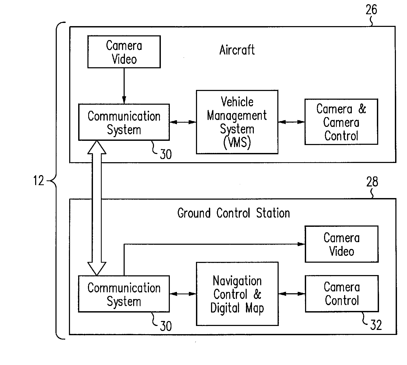
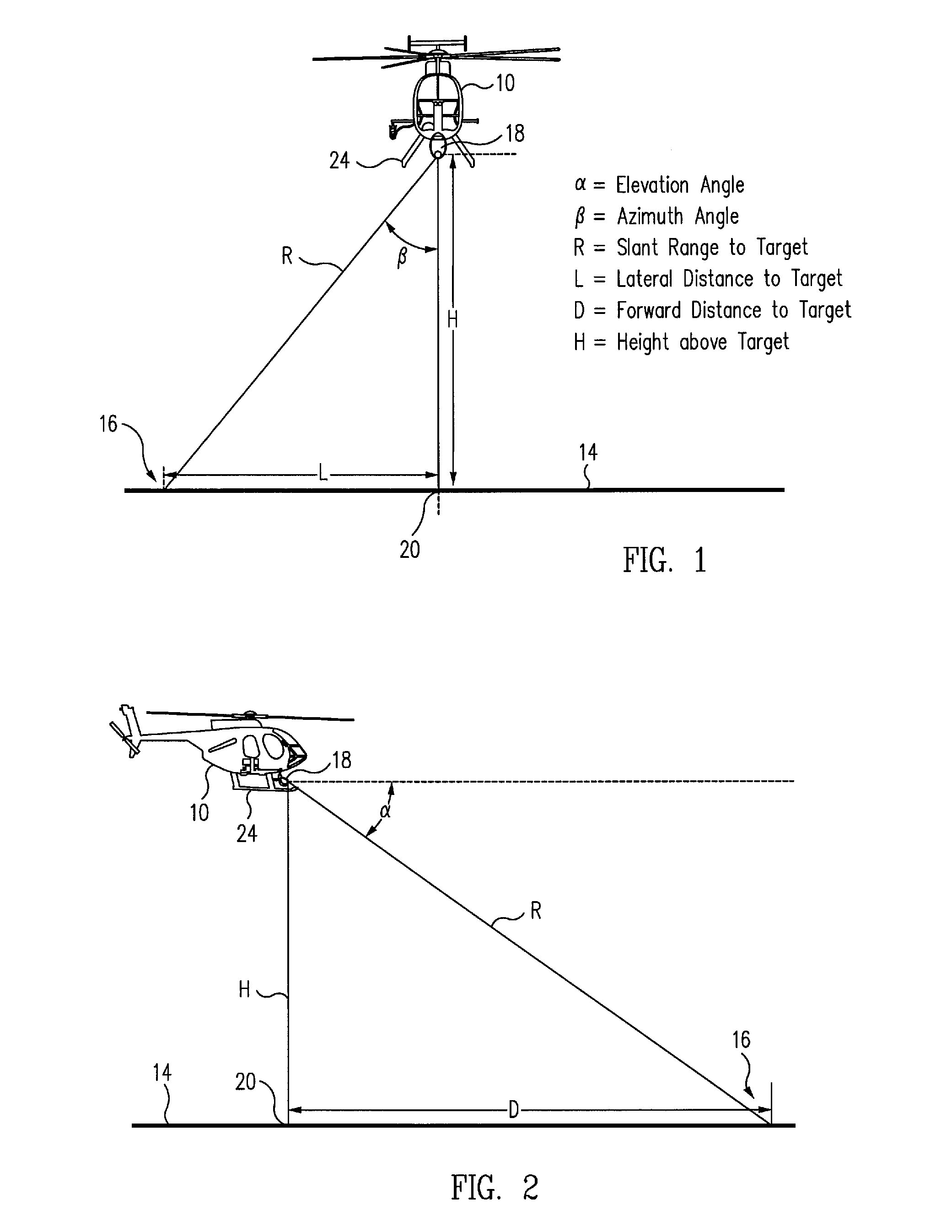
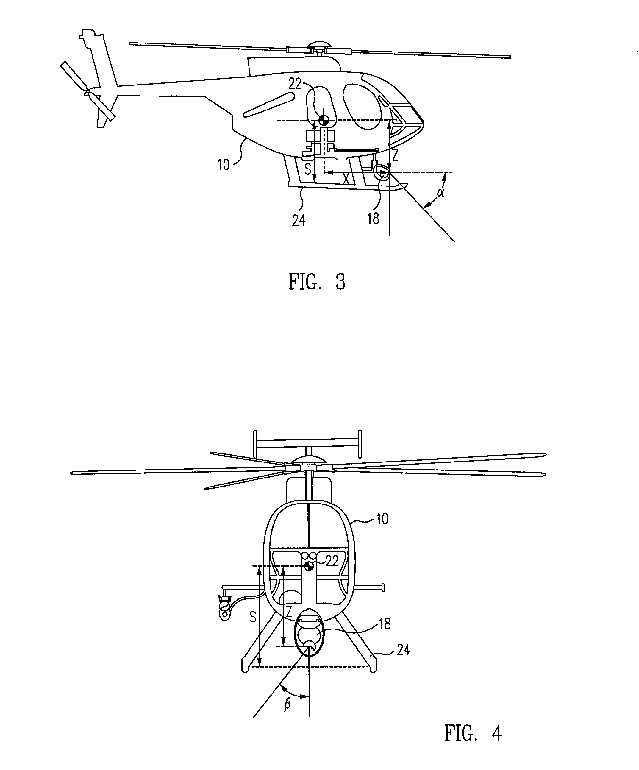
[0028]FIGS. 1 and 2 respectively illustrate front and right side elevation views of an aircraft 10, e.g., a helicopter, equipped with an exemplary embodiment of a command and approach control system 12 (see FIG. 5) in accordance with the present invention, shown operating over a ground or water surface 14 and relative to a selected target point 16 located on the surface 14. The helicopter may be manned, e.g., by a pilot, or may be unmanned and controlled by an operator located at a remote command center.

[0029]The novel command and control system 12 comprises a camera 18, including a rangefinder, preferably a laser rangefinder, disposed aboard the aircraft 10 for measuring an azimuth angle β, an elevation angle a and a line-of-sight (LOS) distance, or slant range, from a fixed point on the aircraft relative to the selected target point 16 on the surface 14 below the aircraft, a conventional navigation system (not illustrated) disposed aboard the aircraft for measuring the latitude an...


PUM


Abstract

An aircraft control system for operations close to the ground includes a camera having a rangefinder for measuring the azimuth, elevation and slant range from a fixed point on the aircraft relative to a selected target point on a surface below the aircraft, a navigation system for measuring the latitude and longitude of the aircraft on the surface, a computer for computing the position of the fixed point on the aircraft relative to the target point from the respective measurements of the camera and the navigation system, and a controller for controlling the movement of the aircraft such that the fixed point is positioned at a selected position above the selected target point on the surface. The controller may also include an automatic tracking mechanism for maintaining the position of the fixed point on the aircraft at the selected position above a moving object.

Description

BACKGROUND[0001]The present disclosure relates to aircraft guidance and control systems, in general, and in particular, to a command and control approach system that enables a manned or unmanned aircraft operating close to the ground or the deck of a moving ship to safely and precisely drop off or pick up an external cargo load that blocks the aircraft's direct, line-of-sight (LOS) sensors to the ground or ship.[0002]In a low-speed, external cargo-hook operation of a helicopter, it is difficult to obtain an accurate above-ground-level (AGL) altitude because the cargo load typically interferes with the usual AGL altitude sensors of the vehicle. Such sensors, including Radar Altitude, Ultrasonic Altitude and Laser Altitude sensors, all provide relatively accurate AGL altitude, but need a direct, line-of-sight path to the ground to determine the distance between, e.g., a cargo hook or the wheels or skids of the helicopter and the ground.[0003]This problem is more exacerbated when opera...

Claims


Application Information

Patent Timeline
IPC IPC(8): G01C23/00G06F17/00
CPCB63B35/50G05D1/0684G01C21/00G01C5/005
Inventor DOCKTER, GREGORY E.CALDWELL, DONALD G.GRAHAM, JASON
Owner THE BOEING CO
Why Eureka
Try Eureka