Parallel spherical mechanism with two degrees of freedom

a spherical mechanism and parallel axis technology, applied in the direction of mechanical control devices, process and machine control, instruments, etc., can solve the problems of high internal mechanical stress, inability to decouple movements about said axes, and general inutility of rotating the body about its own axis of symmetry

Inactive Publication Date: 2008-03-27
EUROPEAN SPACE AGENCY
View PDF14 Cites 6 Cited by
  • Summary
  • Abstract
  • Description
  • Claims
  • Application Information

AI Technical Summary

Benefits of technology

[0019] An object of the invention is to provide a parallel spherical orienting mechanism (“wrist”) having two degrees of freedom that makes it possible to solve the above-mentioned drawbacks of the prior art, at least in part.

Problems solved by technology

When the body for orienting presents an axis of symmetry, turning the body about its own axis of symmetry is generally not useful (it suffices to think of the reflector of a parabolic antenna or a telescope): under such circumstances, which occur frequently in practice, it suffices to use an orienting mechanism having two degrees of freedom.
The main drawbacks of those architectures are the fact that the spherical motion axes are not predetermined, i.e. they are not fixed, neither relative to the base nor relative to the platform, and the movements in rotation about said axes cannot be decoupled.
In addition, the fact that they are intrinsically overconstrained leads to high levels of internal mechanical stress and a major risk of jamming.
In addition, they are bulky.
In addition, the mechanism of M. Carricato and V. Parenti Castelli, and the mechanism of G. Gogu contain prismatic joints that can affect their operation negatively, in particular in space applications (lubrication problems) and in micromechanical applications (high levels of friction).

Method used


Image

  • Parallel spherical mechanism with two degrees of freedom
  • Parallel spherical mechanism with two degrees of freedom
  • Parallel spherical mechanism with two degrees of freedom

Examples


Embodiment Construction

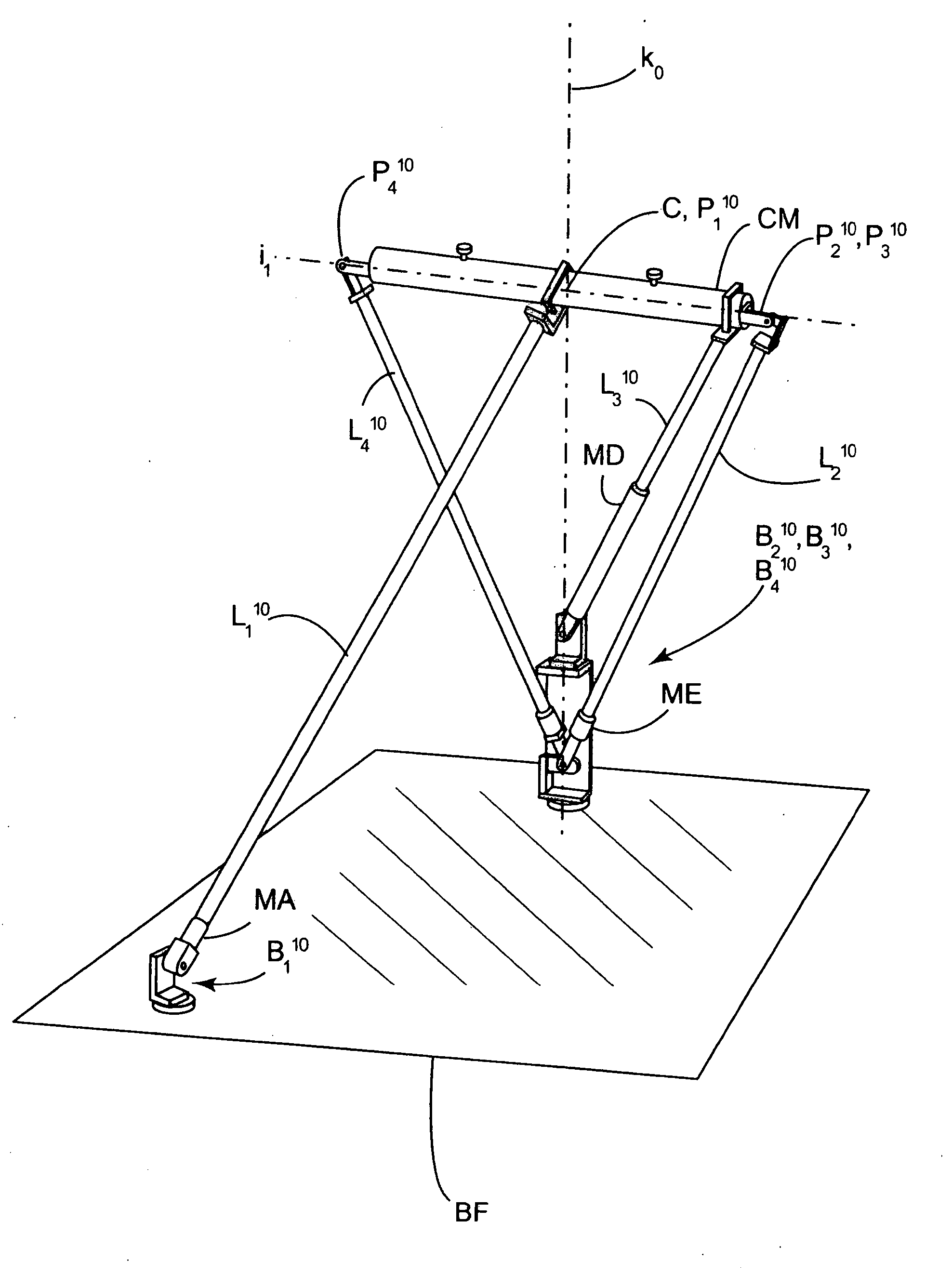
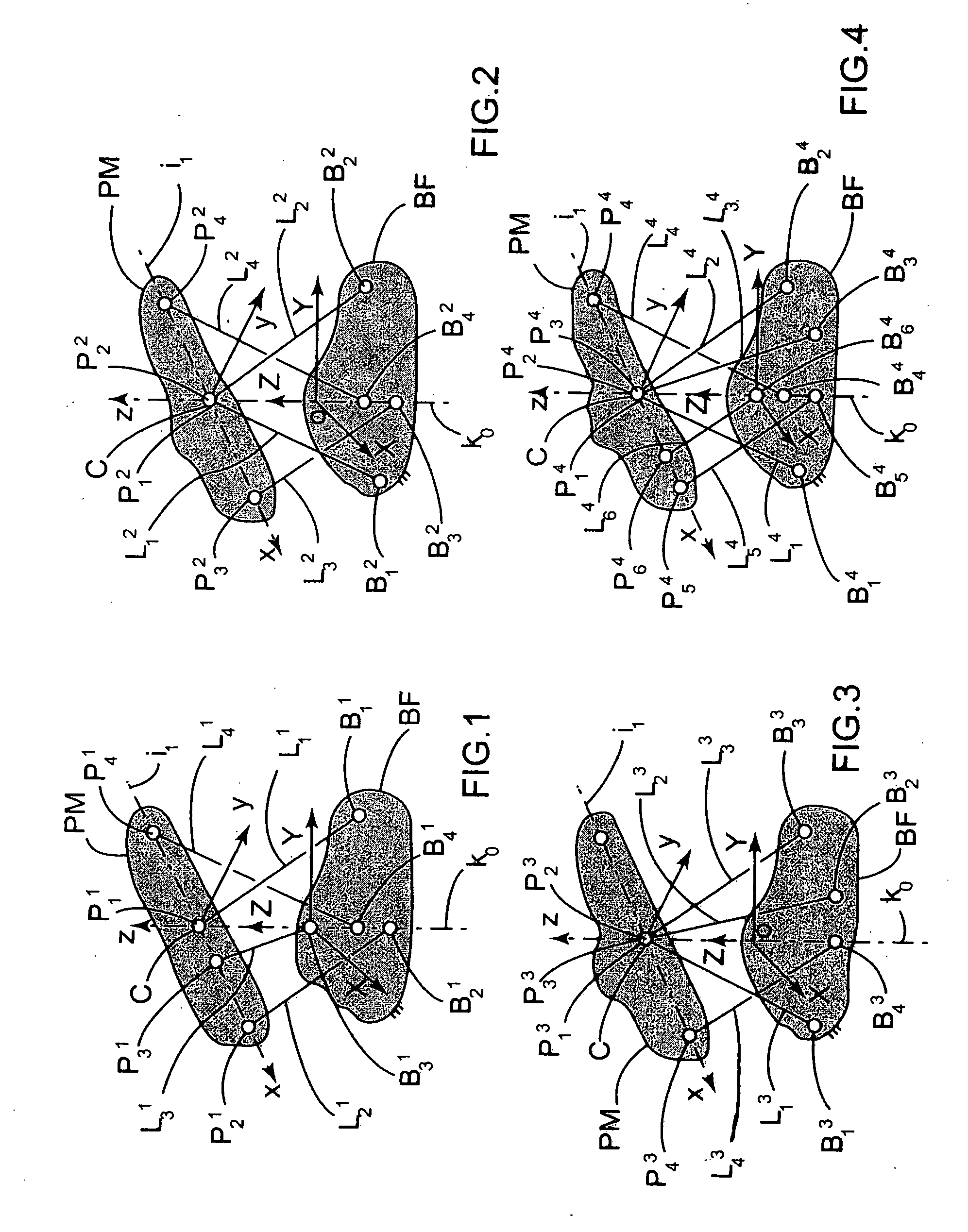
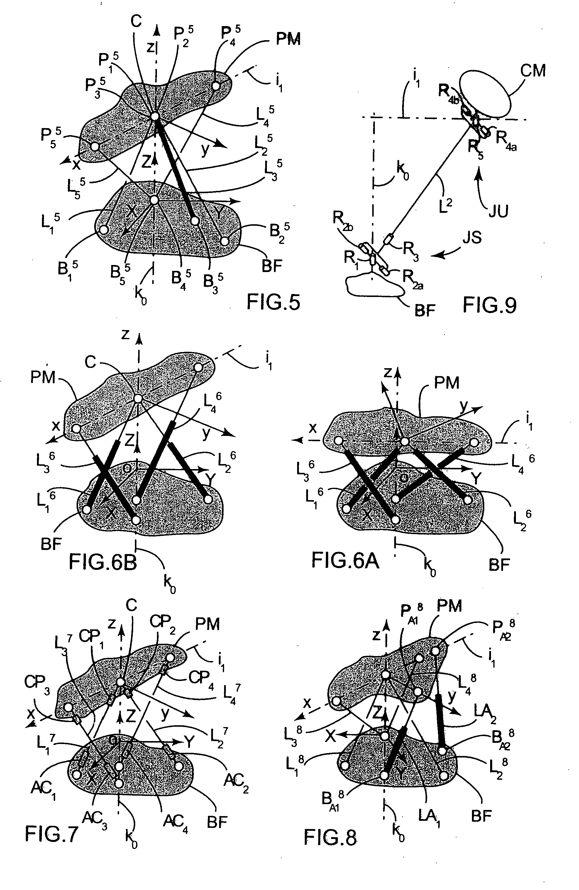
[0050] A mechanism of the invention comprises a fixed base BF, a moving platform PM, and n link elements or “links” L1, L2, . . . , Ln where n is equal to or greater than four (in the figures, a superscript identifies the Figure in question: thus L12 is the first link of FIG. 2). Each link Li is connected to the base BF by a first connection point Bi situated at one of its ends, and to the platform PM by a second connection point Pi situated at its opposite end. A connection point may be a rigid connection (zero degrees of freedom), an elastic connection, or indeed a revolute joint (one degree of freedom in rotation), a universal joint (two degrees of freedom in rotation), or a spherical joint (three degrees of freedom in rotation). The mechanism presents two imposed axes of rotation about which the platform PM can turn: a first axis k0 that is fixed relative to the base PF, and a second axis i1 that is fixed relative to the platform PM. These two axes, which are not necessarily per...


PUM


Abstract

A parallel spherical mechanism with two degrees of freedom for connecting a body to a fixed base in such a manner as to enable it to be oriented in three dimensions by turning about a first axis that is fixed relative to said fixed base, and about a second axis that is fixed relative to said body for orienting, these two axes intersecting at a center of spherical motion situated in said body for orienting, wherein: it comprises at least four links, each of said links being connected to said fixed base via a first connection point and to said body for orienting via a second connection point, and each link belonging to a first type or a second type, there being at least one link of each type, in which: in the link(s) of the first type, the first connection point is at any point of said fixed base, and the second connection point coincides with said center of spherical motion situated in said body for orienting: and in the link(s) of the second type, the first connection point lies on said first axis and the second connection point lies on said second axis, but does not coincide with said center of spherical motion; each connection point of said links lying on said first and/or second axis presents at least one degree of freedom in rotation about said axis.

Description

[0001] The invention relates to a parallel spherical mechanism with two degrees of freedom, the mechanism being of the “wrist” type for connecting a body to a fixed base so as to enable the body to be oriented in three-dimensional space. FIELD OF THE INVENTION [0002] The invention can find numerous practical applications, in particular in the space industry, in robotics, and in medicine. Amongst these applications, mention can be made of systems for pointing mirrors, antennas, or cameras, systems for directing laser beams, manipulators, industrial robots, machine tools, etc. BACKGROUND OF THE INVENTION [0003] Numerous mechanisms known in the prior art enable a body (commonly referred to as a “platform”) to be oriented in three dimensions by being turned about two or three axes. When the body for orienting presents an axis of symmetry, turning the body about its own axis of symmetry is generally not useful (it suffices to think of the reflector of a parabolic antenna or a telescope):...

Claims


Application Information

Patent Timeline
Patent Type & Authority Applications(United States)
IPC IPC(8): G05G11/00
CPCB25J17/0266F16M11/12F16M11/121F16M11/2021Y10T74/20305B25J9/0078Y10T74/20213Y10T74/20329G09B9/12
Inventor VERTECHY, ROCCOMENON, CARLOCASTELLI, VINCENZO PARENTI
Owner EUROPEAN SPACE AGENCY
Why Eureka
Try Eureka