Apparatus, system and method for weighing loads in motion
a technology of a weighing apparatus and a motion, applied in the field of weighing systems, can solve the problems of increasing the effort of loading, over- or under-loading vehicles, and the effort required to measure empty and loaded vehicles separately is greater than the desired effort, and achieves the effect of convenient retrofitting
- Summary
- Abstract
- Description
- Claims
- Application Information
AI Technical Summary
Benefits of technology
Problems solved by technology
Method used
Image
Examples
first embodiment
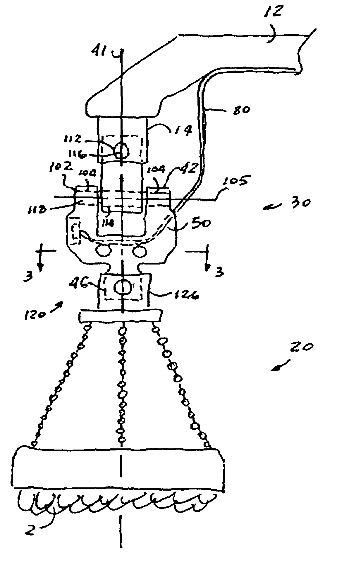
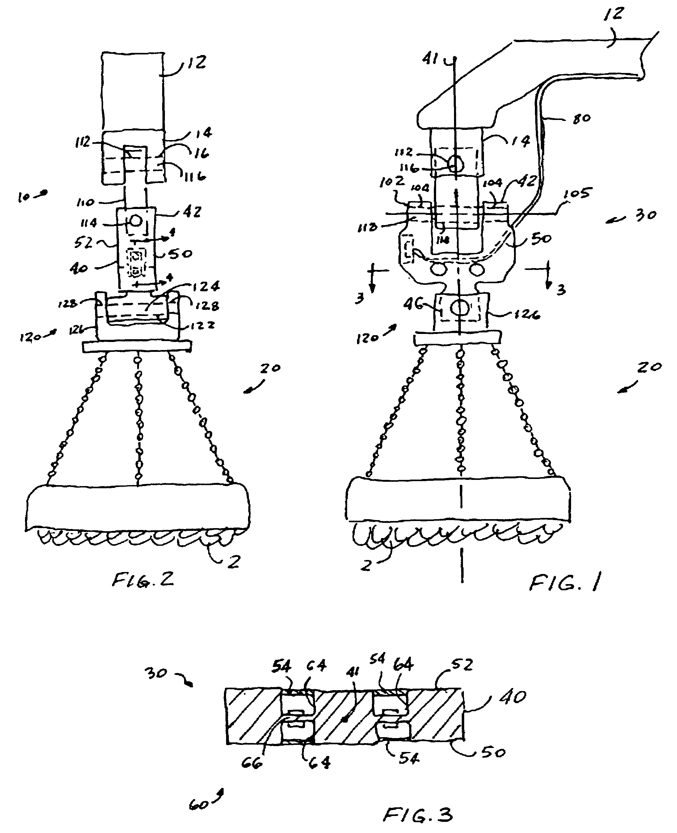
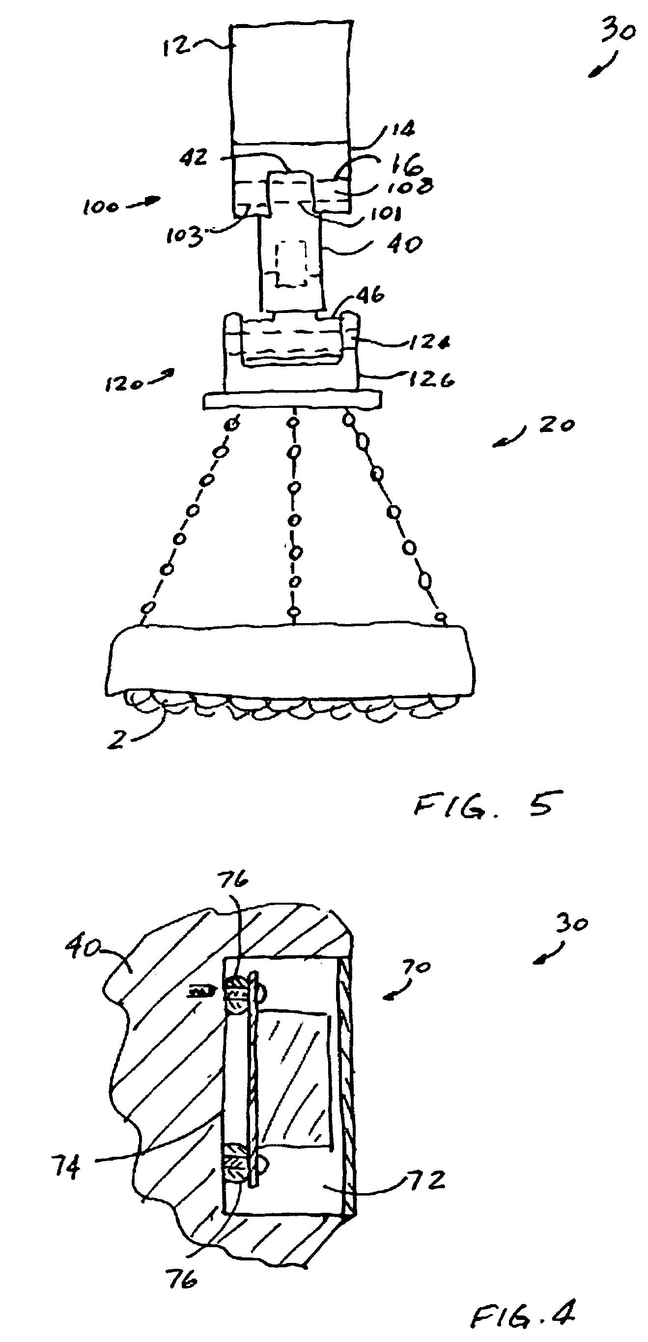
[0027] the present invention provides an apparatus, generally designated as 30, for weighing a load 2 in motion. Now in reference to FIGS. 1-2, the apparatus 30 includes a rigid member 40 having an upper end 42 and a vertically opposed lower end 46 which is oriented toward such load 2 and is axially aligned with the upper end 42. A first vertical surface portion 50 and an opposed second vertical surface portion 52 join the upper end 42 with the lower end 46. The presently preferred material of the rigid member 40 is steel.
[0028]A first measuring means, generally designated as 60, is attached to the rigid member 40 in a vertical and axial alignment with such load 2 for measuring a force exerted by such load 2 onto the rigid member 40 and for generating at least one force measurement signal which characterizes the measured force. As it is well known, such first measuring means includes a strain gage 62 and a cavity 64 formed in the rigid member 40 for mounting such strain gage 62. Alt...
second embodiment
[0038] the invention provides a system for weighing the load 2 in motion, which includes an apparatus 30 having a rigid member 40, a first measuring means 60 for measuring a force exerted by such load 2 onto the rigid member 40 and for generating at least one force measurement signal which characterizes the measured force, a second measuring means 70 for measuring a predetermined parameter associated with a motion of such load 2 and for generating at least one parameter measurement signal which characterizes the measured motion parameter and a signal transmitting means 80 which is coupled to the first measuring means 60 and to the second measuring means 70. The system further includes control means 90, best shown in FIGS. 6-7, which receives the at least one force measurement signal and the at least one parameter measurement signal by way of the signal transmitting means 80. Preferably, the control means 90 includes a microprocessor 92 for executing the predetermined logic algorithm...
third embodiment
[0050] the invention provides a method of dynamically weighing a load 2 in motion. Such method includes the step of measuring a force exerted by the load 2 onto the load moving apparatus 12. Then, providing at least one force measurement signal which characterizes the measured force to the control means 90 capable of executing a predetermined logic algorithm. Next, measuring a parameter associated with the motion of the load 2. Providing at least one motion parameter measurement signal which characterizes the measured motion parameter to the control means 90. Next, defining, by the control means 90, a steady state condition during the motion of the load 2. Finally, determining a mass of the load 2 during the steady state condition.
[0051]In the presently preferred embodiment of the invention, the steady state condition is defined by incrementally calculating a change of the measured mass over time and determining when the change is within a predetermined threshold. The method contemp...
PUM
 Abstract
Description
Claims
Application Information
 - R&D
- Intellectual Property
- Life Sciences
- Materials
- Tech Scout
- Unparalleled Data Quality
- Higher Quality Content
- 60% Fewer Hallucinations
Browse by: Latest US Patents, China's latest patents, Technical Efficacy Thesaurus, Application Domain, Technology Topic, Popular Technical Reports.
© 2025 PatSnap. All rights reserved.Legal|Privacy policy|Modern Slavery Act Transparency Statement|Sitemap|About US| Contact US: help@patsnap.com


