
Electromagnetic Lock with Strong Anti-impact Ability

Inactive Publication Date: 2008-03-27
MIN HAO
View PDF5 Cites 21 Cited by
  • Summary
  • Abstract
  • Description
  • Claims
  • Application Information

AI Technical Summary

Benefits of technology

[0007]The purpose of the present invention is to solve the problem of the weakness of the lockpins for current electromagnetic lock, to design a stronger electromagnetic lock, which can survive under very strong wallop, and can transfer the destroy power into a reinforced rib.
[0013]The electromagnet uses permanent magnets to increase magnetic forces. The design also can increase third spring rate, thereby to get bigger lockpin.
[0015]1. This invention solves the problem of the weakness of electromagnetic locks in current market, the new electromagnetic locks can guarantee no any break or distortion under 1000 kg wallop. The safety grade is increased greatly.
[0016]2. This invention uses lever principle to reduce the force acting on lockpin, thereby the safety grade for the slipping block and lockpin is increased.
[0017]3. This invention simplifies the lock structure, and makes producing process easy.

Problems solved by technology

Currently, safety boxes for banks, jewelry business, and firearms business etc., all use electromagnetic lock with fingerprint identification to achieve safety purpose, unauthorized users cannot open it with normal methods.
However, consider that the relatively weakness of the electromagnet force and the gravitation acceleration of the bolt, the lockpin cannot be designed very strong.
Therefore, the lockpin is easy broken.
This is the main hidden trouble of the safety.

Method used


Image

  • Electromagnetic Lock with Strong Anti-impact Ability
  • Electromagnetic Lock with Strong Anti-impact Ability
  • Electromagnetic Lock with Strong Anti-impact Ability

Examples


Embodiment Construction

[0020]The accompanying drawings facilitate understanding of the various embodiments of this invention. In such drawings:

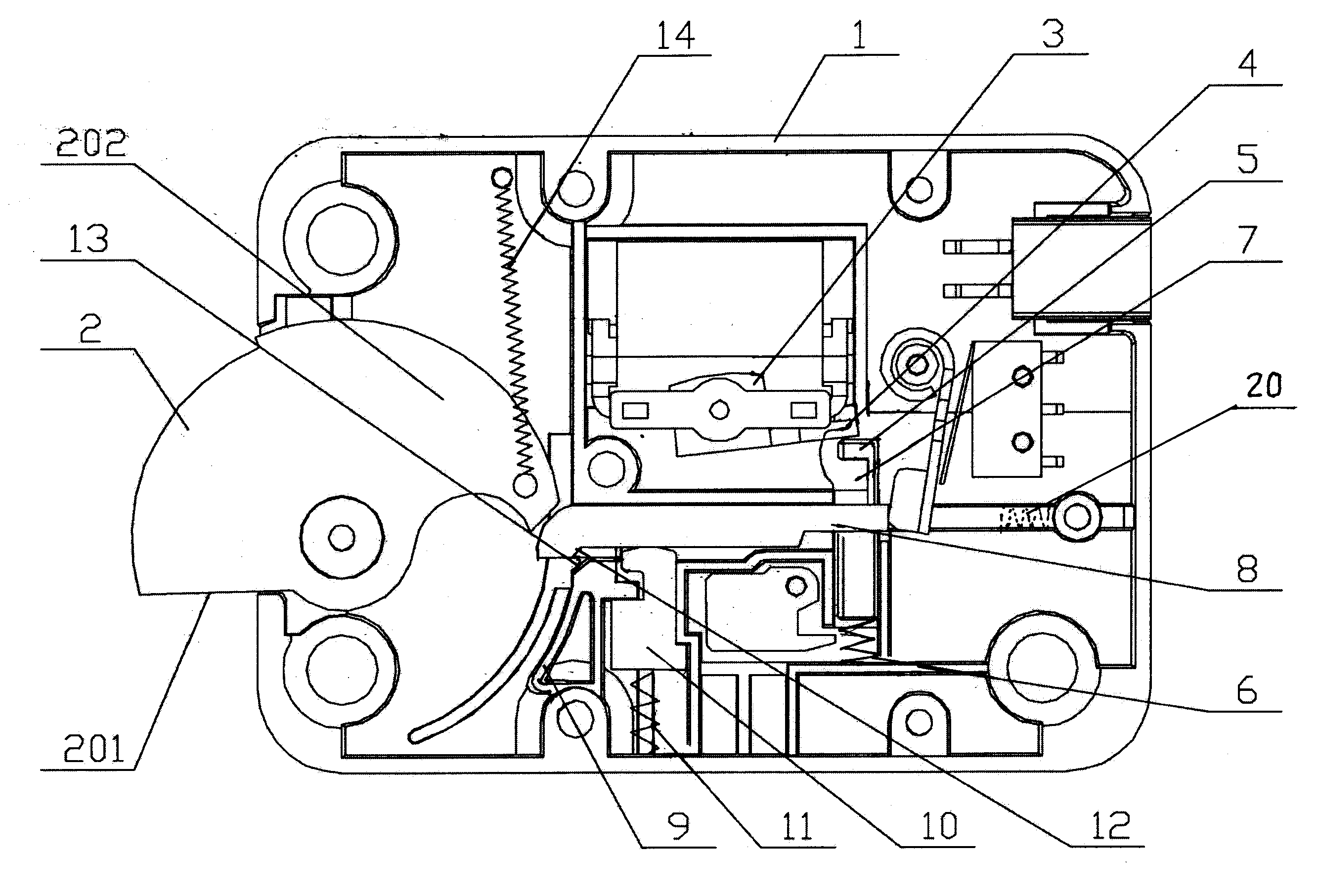
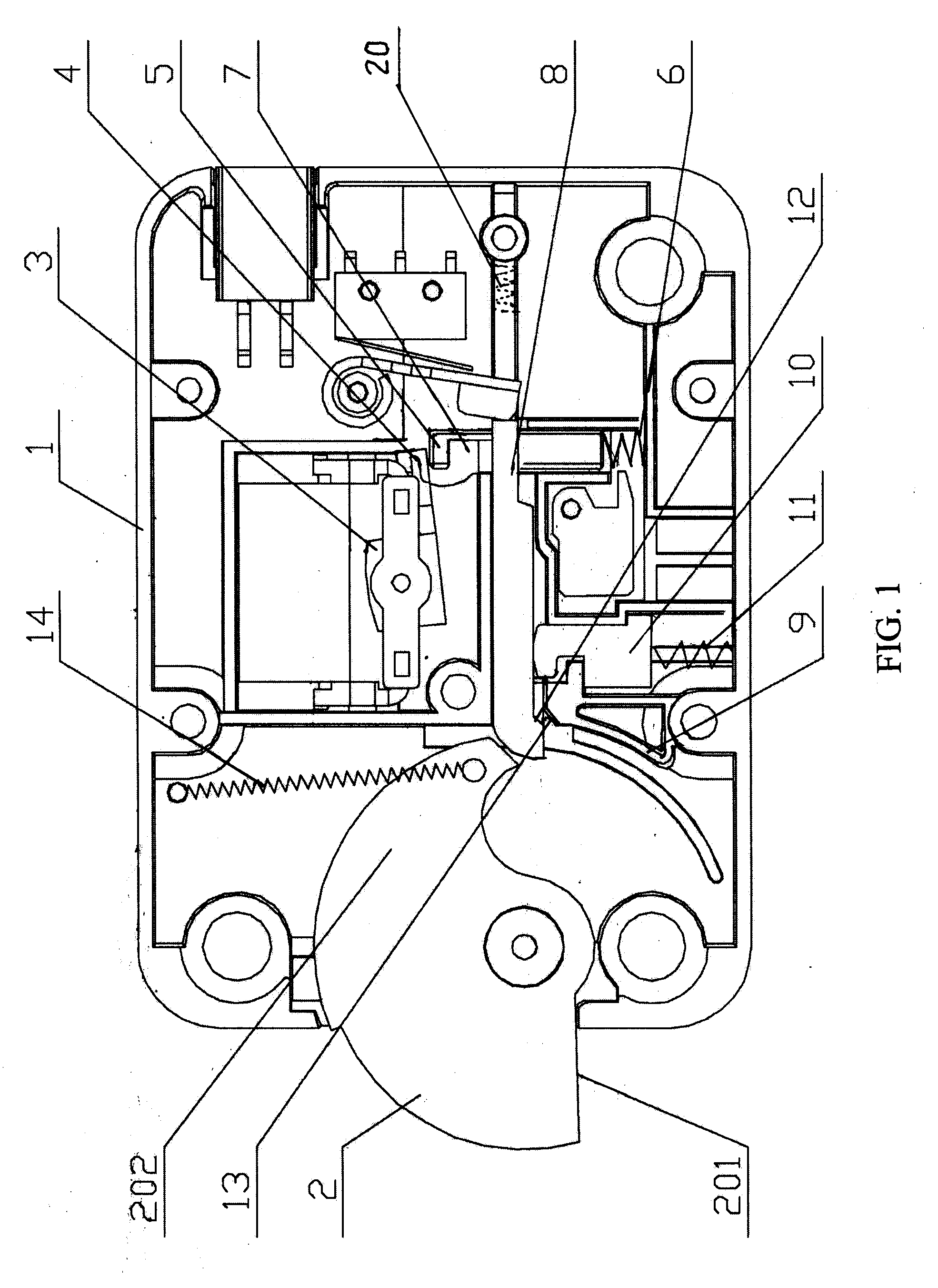
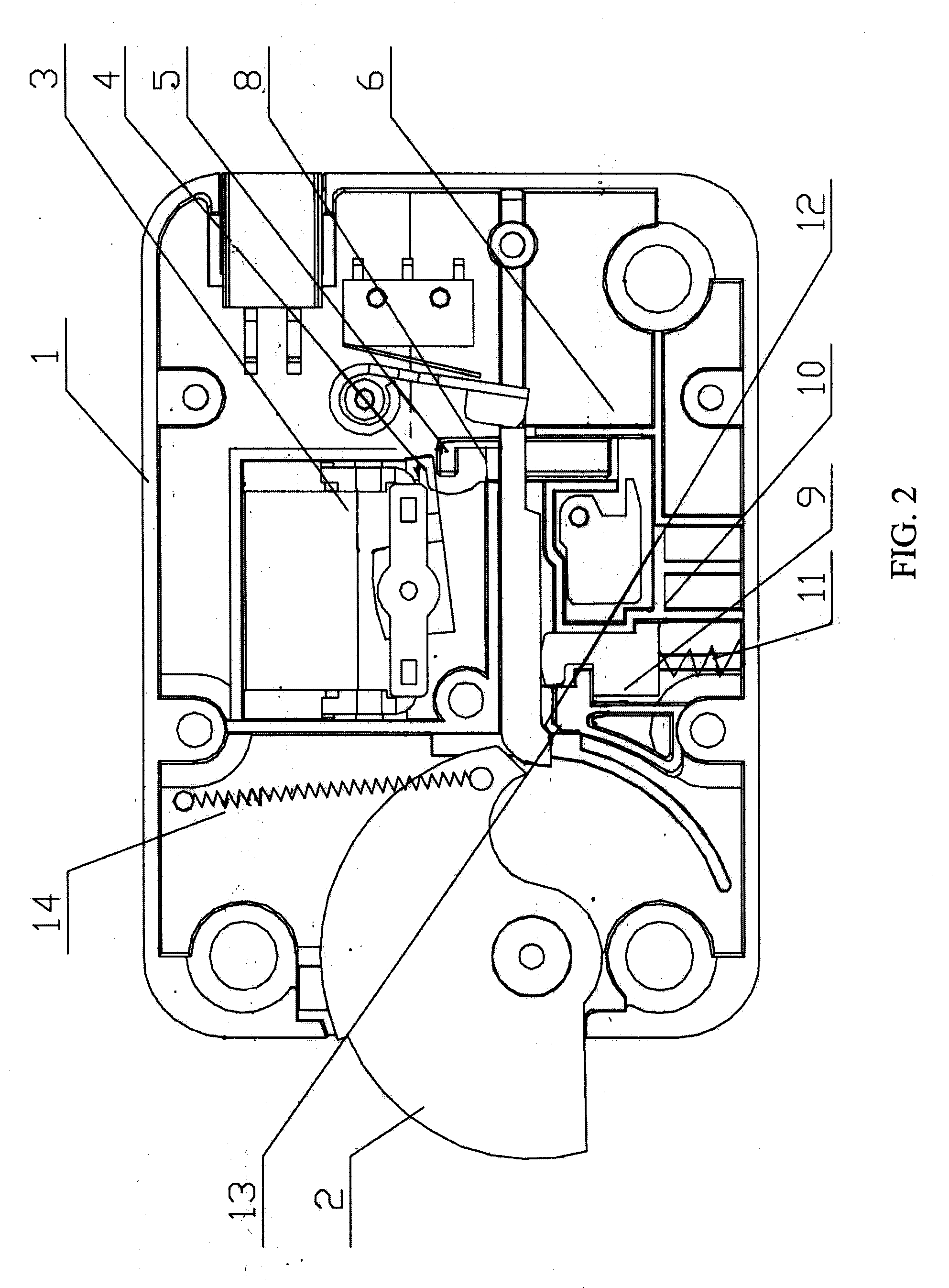
[0021]Refer to FIG. 1, it shows the body structure of an electromagnetic lock, which includes a lock shell (1), an arc style bolt (2), an electromagnet (3). The are style bolt (2) is pivoted assembled in the lock shell (1), the bolt head (201) of the arc style bolt (2) is outside of the lock shell (1), the bolt tail (202) of the arc style bolt (2) is located inside the lock shell (1) connected a first reposition spring (14), other end of which is fixed with the lock shell.

[0022]The electromagnet (3), which adapts permanent magnets, is installed inside the lock shell (1). An implemental part (4) (action like a lever structure) of the electromagnet (3) withstands one end of a lockpin (5), another end of the lockpin (5) touches with a third spring (6), the lockpin and third spring are restricted in a guide slot on the lock shell (1).

[0023]Also, there has a unlock slot...


PUM


Abstract

The present invention resolves the problem that a lockpin is easy to broken in current electromagnetic lock, find a good structure for greatly improving the capability of the electromagnetic lock against a very strong impact from outside. The new structure can transfer the outside force to a reinforced rib on the lock shell. The new electromagnetic lock comprises a lock shell (1), an arc style bolt (2), an electromagnet (3), an implemental part (4) of the electromagnet (3) connecting with one end of the lockpin (5), a unlock slot (7) is on the lockpin (5), a slipping block (8) is installed in a slipping slot against the lockpin, other end of this slipping block is against the bolt tail (202) of the arc style bolt. A second spring (20) is installed between the bottom of the slipping slot and the slipping block (8), the second spring (20) forces the slipping block (8) to contact the bolt tail (202) of arc style bolt. The structure of the new electromagnetic lock is simple, the manufacturing process is easy, and the new electromagnetic lock can resist relatively stronger wallop.

Description

CROSS REFERENCE TO THE RELATED PATENT APPLICATION [0001]This patent application claims the priority of the Chinese patent application No. 200620077575.4, filed on Sep. 25, 2006.FIELD OF THE INVENTION [0002]This invention relates to a new style electromagnetic lock, which is sustainable a wallop over one ton.BACKGROUND OF THE INVENTION [0003]Currently, safety boxes for banks, jewelry business, and firearms business etc., all use electromagnetic lock with fingerprint identification to achieve safety purpose, unauthorized users cannot open it with normal methods. Therefore, anti-impact-ability is a main concern for electromagnetic locks, which are required to suffer a wallop over one ton without any damage for a safety purpose.[0004]Most electromagnetic locks in current market use electromagnet to open or close the lock. For example, when electromagnet is on power or off power, a lockpin can plug into or pull out from slipping block, which controls a bolt, to open or lock the electroma...

Claims


Application Information

Patent Timeline
IPC IPC(8): E05C3/06
CPCE05B9/00E05B17/2084E05B47/0002E05B2047/0093E05B63/0013E05B65/0075E05B47/0603Y10T292/1082
Inventor MIN, HAO
Owner MIN HAO
Learn More