Bent folded dipole antenna for reducing beam width difference

a dipole antenna and beam width technology, applied in the direction of antennas, polarised antenna unit combinations, antenna feed intermediates, etc., can solve the problems of complex antenna structure, increased antenna cost, and difficult impedance matching, so as to reduce the manufacturing cost of the antenna and simplify the antenna structure.

Inactive Publication Date: 2008-03-27
ACE ANTENNA
View PDF9 Cites 36 Cited by
  • Summary
  • Abstract
  • Description
  • Claims
  • Application Information

AI Technical Summary

Benefits of technology

[0008]Accordingly, the present invention has been made keeping in mind the above problems occurring in the prior art, and an object of the present invention is to provide a bent folded dipole antenna, in which a plurality of bent folded dipole components, each made of a metal plate or a copper plate, forms a bent folded dipole antenna unit, so that the bent folded dipole antenna unit is implemented as a single pattern, thus simplifying the structure of the antenna and consequently reducing the manufacturing cost thereof.

Problems solved by technology

However, since the conventional technology discloses a structure in which four dipoles, formed in a dipole square, are equally divided and separated, there is a problem in that the structure of the antenna is complicated, and the cost of the antenna increases due to the complicated structure.
There is another problem in that, since the conventional antenna is composed of four equally divided dipoles and two symmetrical pairs of feeding units, impedance matching is not easily performed, and wide band characteristics and antenna gain are deteriorated.
There is a further problem in that, in the case of a typical dipole antenna, such as the conventional antenna, as the frequency band is widened, a beam width difference increases, thus it is difficult to provide consistent speech quality for different frequencies.

Method used


Image

  • Bent folded dipole antenna for reducing beam width difference
  • Bent folded dipole antenna for reducing beam width difference
  • Bent folded dipole antenna for reducing beam width difference

Examples


Embodiment Construction

[0033]Hereinafter, embodiments of the present invention will be described in detail with reference to the attached drawings.

[0034]Reference now should be made to the drawings, in which the same reference numerals are used throughout the different drawings to designate the same or similar components.

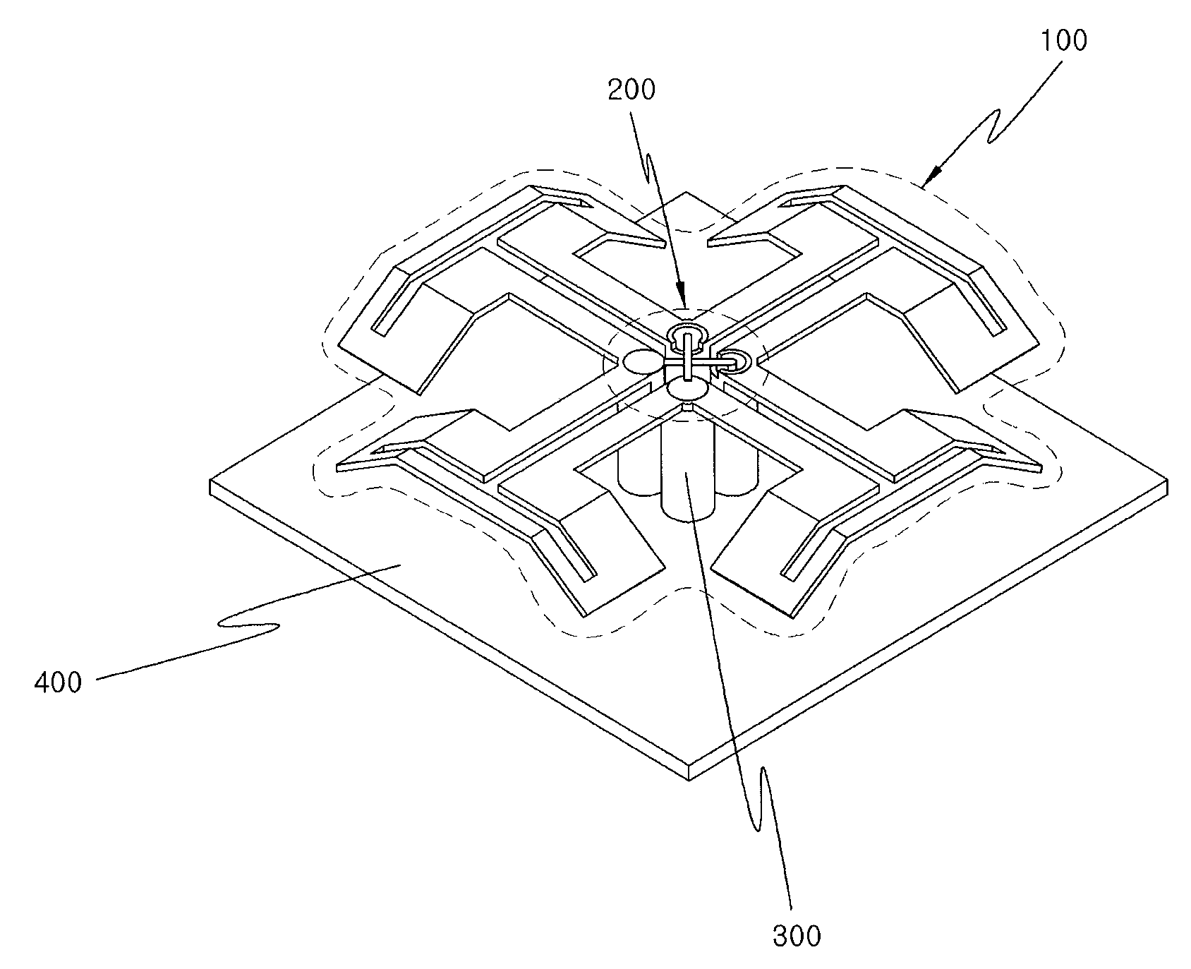
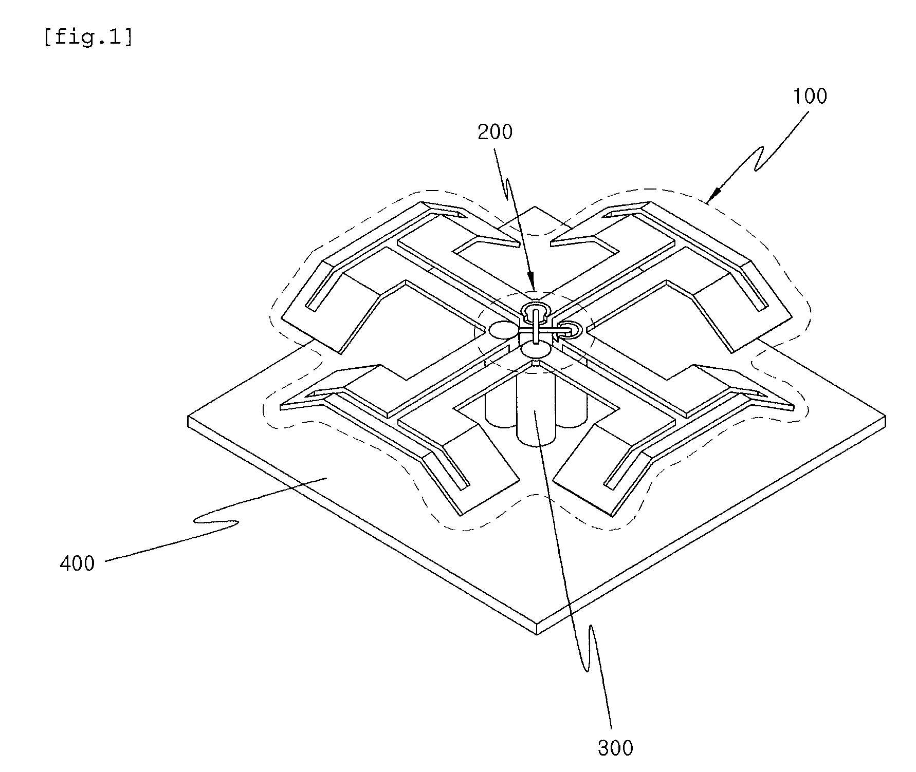
[0035]FIG. 1 is a perspective view showing a bent folded dipole antenna for reducing a beam width difference according to an embodiment of the present invention. The bent folded dipole antenna includes a bent folded dipole antenna unit 100 formed in such a way that first to fourth bent folded dipole components for reducing a beam width difference are connected to each other as a single pattern, a feeding unit 200 connected to the bent folded dipole antenna unit 100 and adapted to feed a signal, a balloon unit 300 adapted to support and fasten both the bent folded dipole antenna unit 100 and the feeding unit 200, and a ground unit 400 formed on the bottom of the balloon unit 300.

[0036]In d...


PUM


Abstract

The present invention relates to a bent folded dipole antenna for reducing a beam width difference, which can reduce a beam width difference, varying with a frequency band, and generate dual polarization through the use of an antenna structure having a bent folded dipole antenna unit, in which a plurality of bent folded dipole components is connected to each other as a single pattern, and a feeding unit for feeding a signal to the folded dipole antenna unit.
Therefore, the present invention is advantageous in that it can reduce a beam width difference varying with a frequency band, simplify the structure of the antenna to reduce the cost thereof, and easily obtain dual polarization characteristics and wide band characteristics by combining a feeding unit for feeding a signal in a dual feeding manner with the bent folded dipole antenna unit implemented as a single pattern. In addition, the present invention is advantageous in that current flowing into the feed point of the feeding unit is induced only in folded dipole components without flowing into another feed point, thus realizing excellent isolation characteristics.

Description

BACKGROUND OF THE INVENTION[0001]1. Field of the Invention[0002]The present invention relates, in general, to a bent folded dipole antenna for reducing a beam width difference and, more particularly, to a bent folded dipole antenna, which reduces a beam width difference and has dual polarization characteristics and wide band characteristics, thanks to a structure in which a bent folded dipole antenna unit, which is formed of a plurality of bent folded dipole components each made of a metal plate or a copper plate and is implemented as a single pattern, is combined with a feeding unit for feeding a signal in a dual feeding manner.[0003]2. Description of the Related Art[0004]As conventional technology for a dual-polarized dipole antenna, a dual-polarized dipole antenna disclosed in Korean Patent Laid-Open Publication No. 2001-0040623 radiates polarization to a structurally prescribed alignment of dipoles at an angle of +45° or −45°. The end of the symmetrical, or substantially or appr...

Claims


Application Information

Patent Timeline
Patent Type & Authority Applications(United States)
IPC IPC(8): H01Q9/26
CPCH01Q9/26H01Q21/26H01Q21/24H01Q21/062
Inventor LEE, SEUNG-CHULJIN, JAE-SUNKIM, MYUNG-KUK
Owner ACE ANTENNA
Why Eureka
Try Eureka