
Display with infrared backlight source and multi-touch sensing function

Active Publication Date: 2008-03-27
LG DISPLAY CO LTD
View PDF16 Cites 307 Cited by
  • Summary
  • Abstract
  • Description
  • Claims
  • Application Information

AI Technical Summary

Problems solved by technology

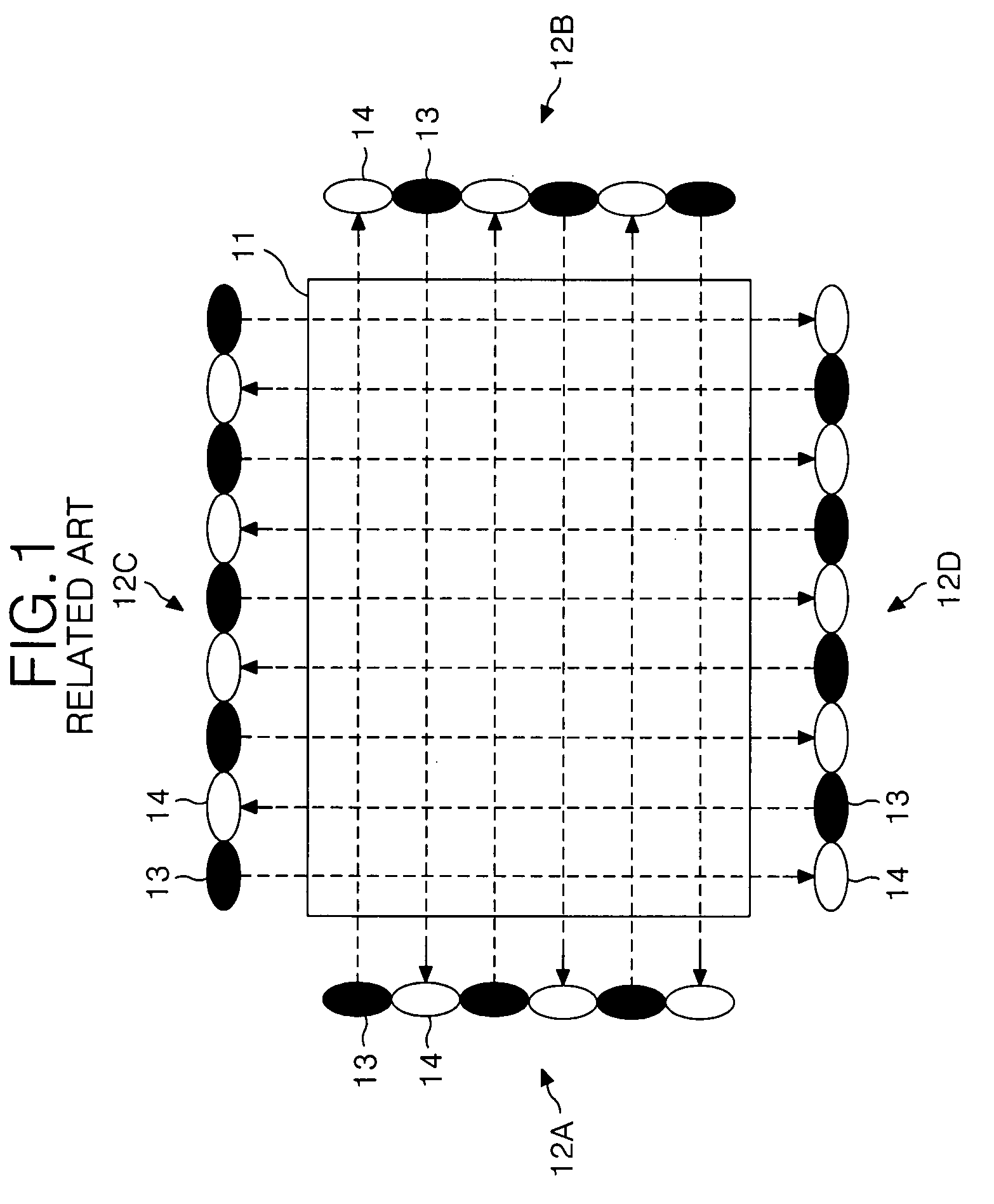
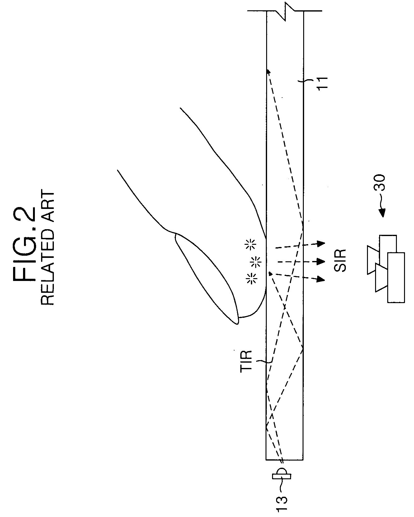
However, the multi-touch device of the related art is disadvantageous because the multi-touch recognition capability is inaccurate due to a direct illumination by infrared light.
Furthermore, since the multi-touch device in FIG. 2 and FIG. 3 displays an image using a projector, the type of display device and the design of the display device is limited.
Additionally, the life span of a the projection lens is limited.
Thus, the system is complicated, the space occupied by the components is large, and a signal transmitting path is long.

Method used


Image

  • Display with infrared backlight source and multi-touch sensing function
  • Display with infrared backlight source and multi-touch sensing function
  • Display with infrared backlight source and multi-touch sensing function

Examples


Embodiment Construction

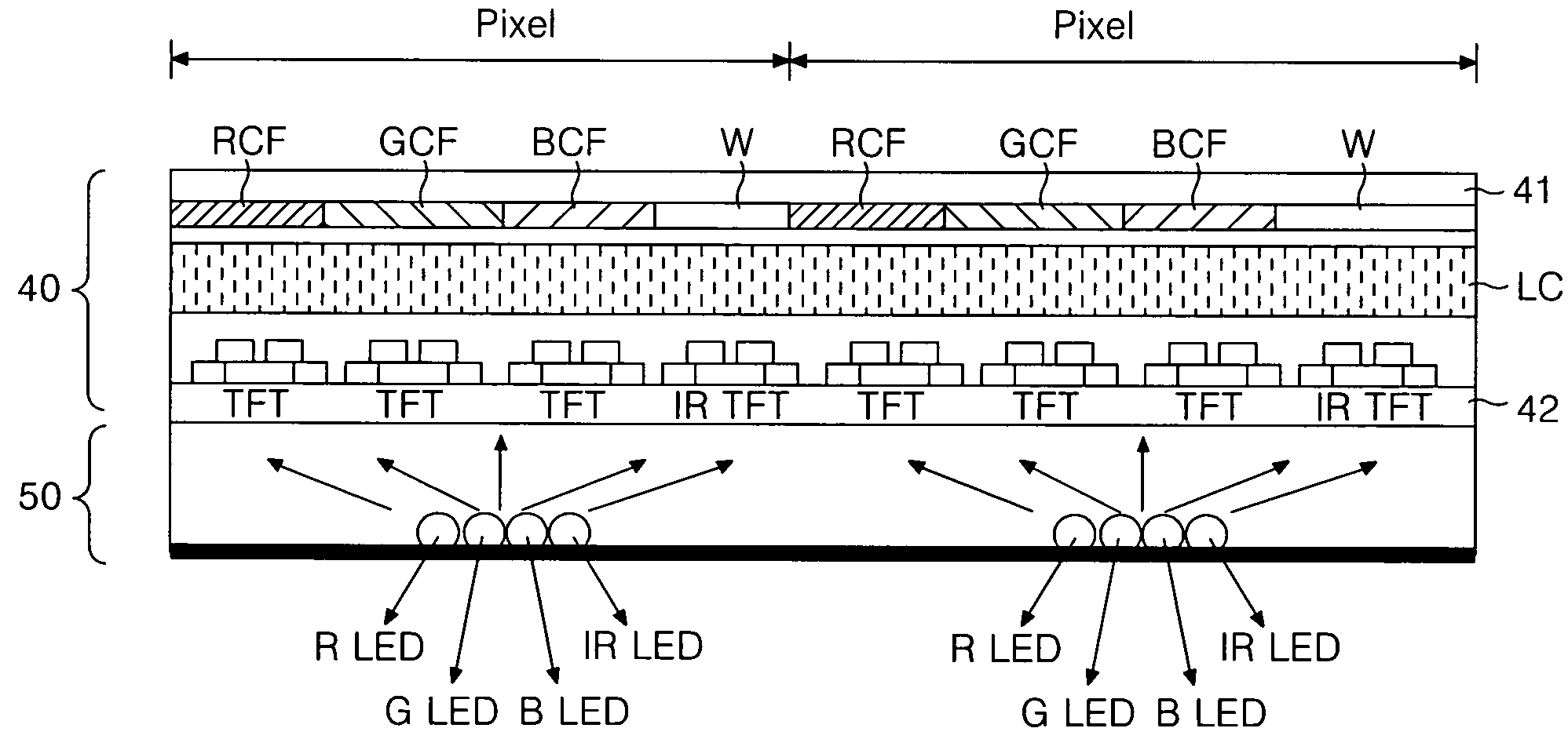
[0024]Referring to FIG. 4, a display having a multi-touch sensing function includes a display panel 40 and a backlight unit 50 having an infrared light source. The display panel 40 includes an upper transparent substrate 41, a lower transparent substrate 42, and a liquid crystal layer LC. The upper transparent substrate 41 has color filters RCF, GCF, and BCF and a transparent window W, which are formed at the same layer. The lower transparent substrate 42 has a pixel thin film transistor (TFT) that selects a pixel, and a TFT for sensing an infrared ray (IR TFT). The liquid crystal layer LC is formed between the upper transparent substrate 41 and the lower transparent substrate 42. It is desirable that the upper / lower transparent substrates 41 and 42 are formed of a glass substrate because a plastic substrate, such as an acrylic plate, is relatively thick, has a wide diffusing angle upon touching, and is easily damaged or scratched.

[0025]A plurality of data lines and a plurality of g...


PUM


Abstract

A touch-sensing display screen includes an upper transparent substrate, a lower substrate opposite the upper substrate, and a backlight unit having an infrared light source configured to radiate infrared light through the upper substrate in a first direction. A transparent window is disposed in alignment with the infrared light source and between the upper and lower transparent substrates. A portion of the infrared light radiated in the first direction is reflected back through the upper substrate and through the transparent window in a second direction by an object touching a surface of the upper transparent substrate. A pixel thin-film transistor on the lower substrate is configured to activate a pixel electrode, and an infrared light-sensing thin-film transistor is configured to sense the infrared light received through the upper substrate in the second direction, and output an infrared light-sense signal in response thereto.

Description

[0001]This application claims the benefit of Korean Patent Application No. P2006-093712 filed on Sep. 26, 2006, which is hereby incorporated by reference.BACKGROUND[0002]1. Field of the Invention[0003]The present invention relates to a display, and more particularly to a display that is capable of multi-touch sensing, and a driving method thereof.[0004]2. Description of the Related Art[0005]Generally, a touch panel is a type of user interface that may be attached to a surface of a display device, where an electrical characteristic is changed at a touch area where a finger of the user or other instrument contacts the touch panel so as to sense the touch area thereof. The application for touch panels extend to small portable terminals, office equipment and the like. If two or more touches are simultaneously generated, the touch panel might malfunction or any one of the touches may be selected by a pre-set program.[0006]FIGS. 1-3 show known multi-touch devices that have attempted to ov...

Claims


Application Information

Patent Timeline
IPC IPC(8): G06F3/042G06F3/038G06F3/041
CPCG02F1/13338G02F1/1368G06F3/0412G02F2203/11G06F3/0421G02F2001/13312G02F1/13312G09G3/36
Inventor CHUNG, IN JAEAHN, IN HOBAE, SANG HYUCK
Owner LG DISPLAY CO LTD
Learn More