Image blurring correction unit, image blurring correction apparatus, and imaging apparatus

a technology of image blurring and correction apparatus, which is applied in the field of image blurring correction apparatus, imaging apparatus, can solve the problems of increasing the size of the camera shake correction mechanism, reducing the effect of blurring

Inactive Publication Date: 2008-03-27
FUJI PHOTO OPTICAL CO LTD
View PDF16 Cites 16 Cited by
  • Summary
  • Abstract
  • Description
  • Claims
  • Application Information

AI Technical Summary

Benefits of technology

[0022]In a case where the holding module holds only the lens, a structure for holding an image sensor at a rear end portion of the holding module is additionally needed. In a case where the holding module holds the lens and an image sensor, a holding portion for the image sensor is omitted. Thus, the size of the holding module can further be reduced.
[0024]Thus, the holding module can be put into various positions by driving the holding module using the first axis and the second axis as drive axes that are independent of each other. Consequently, in a case where an image blurring correction apparatus having this image blurring correction unit and a blurring detection sensor is constructed, the holding module can be adjusted to any position according to a blurring detected by the blurring detection sensor so that the detected blurring is eliminate.
[0026]In the case of using what is called a voice coil motor having the magnet, which forms a magnetic field, and the coil placed in the magnetic field and is energized to generate a force of turn-driving the holding module, both of the first drive portion and the second drive portion can be miniaturized. Consequently, the invention can obtain a larger effect in miniaturizing the entire image blurring correction unit.
[0028]Thus, the structure of the bearing portion is simplified and miniaturized. Consequently, the invention can obtain a larger effect in miniaturizing the entire image blurring correction unit.
[0030]Thus, each of the drive points serves also as a bearing portion. Accordingly, the structure is simplified. Consequently, the invention can obtain a larger effect in miniaturizing the entire image blurring correction unit.
[0034]To achieve the foregoing object, according to still another aspect of the invention, there is provided an imaging apparatus comprising the image blurring correction apparatus of the invention. The imaging apparatus features that the imaging apparatus generates image data representing an image, in which blurring is reduced, by capturing light from an object and by causing the image blurring correction apparatus to operate.

Problems solved by technology

Inevitably, the camera shake correction mechanism tends to increase the size thereof.
This camera shake correction mechanism has a drawback that in a case where the size of the camera shake correction mechanism is forcibly reduced, bearings and so on of the rotary joints become fragile.

Method used


Image

  • Image blurring correction unit, image blurring correction apparatus, and imaging apparatus
  • Image blurring correction unit, image blurring correction apparatus, and imaging apparatus
  • Image blurring correction unit, image blurring correction apparatus, and imaging apparatus

Examples


Embodiment Construction

[0046]Hereinafter, preferred embodiments of an image blurring correction unit and an image blurring correction apparatus having the image blurring correction unit according to the invention are described in detail with reference to FIGS. 1 to 9D. Incidentally, the embodiments described below are specific examples of the image blurring correction unit and the image blurring correction apparatus having the image blurring correction unit according to the invention. Therefore, various preferable technical limitations are applied to the embodiments. However, unless a description of specifically limiting the invention is made in the following description, the scope of the invention is not limited to the embodiments.

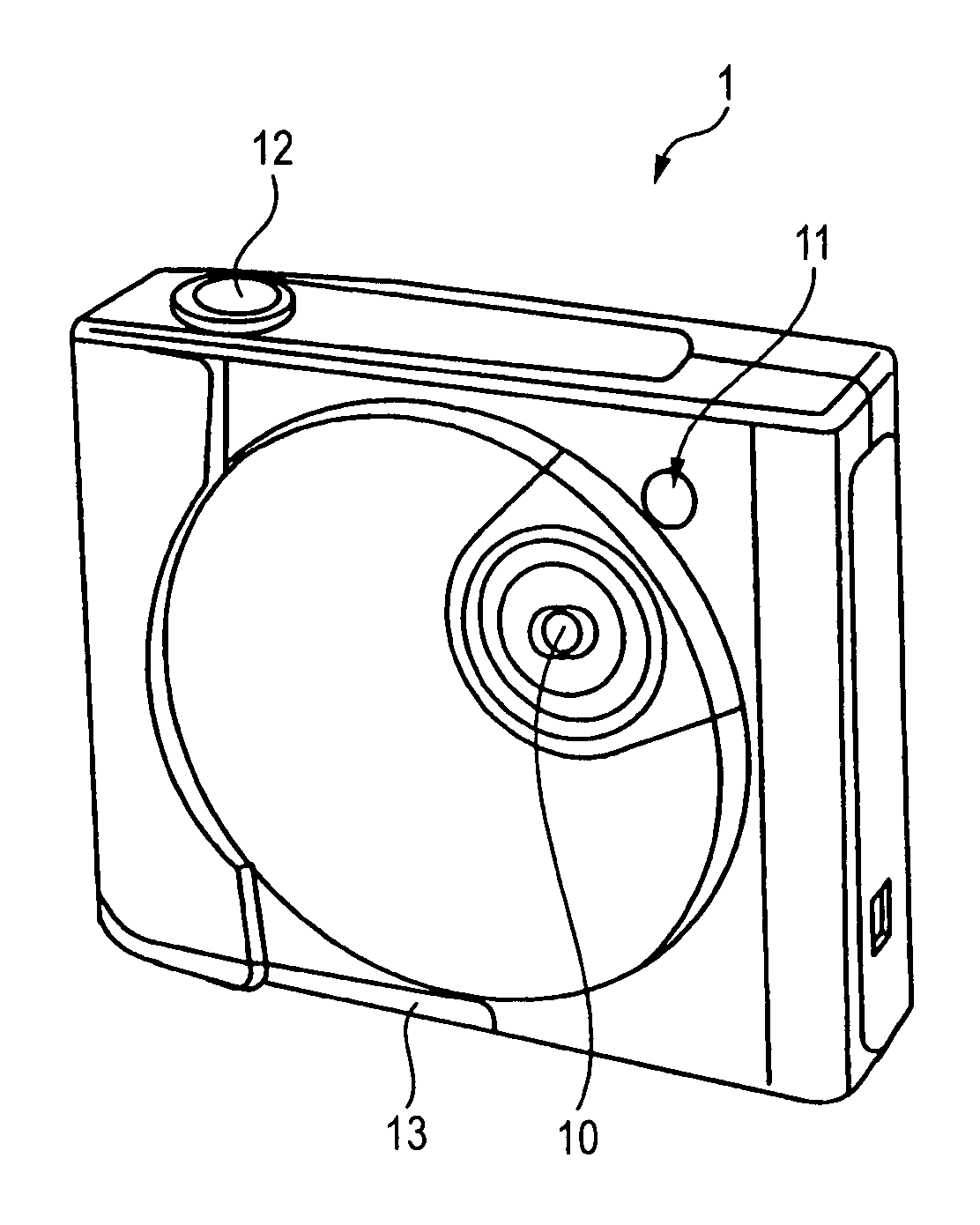
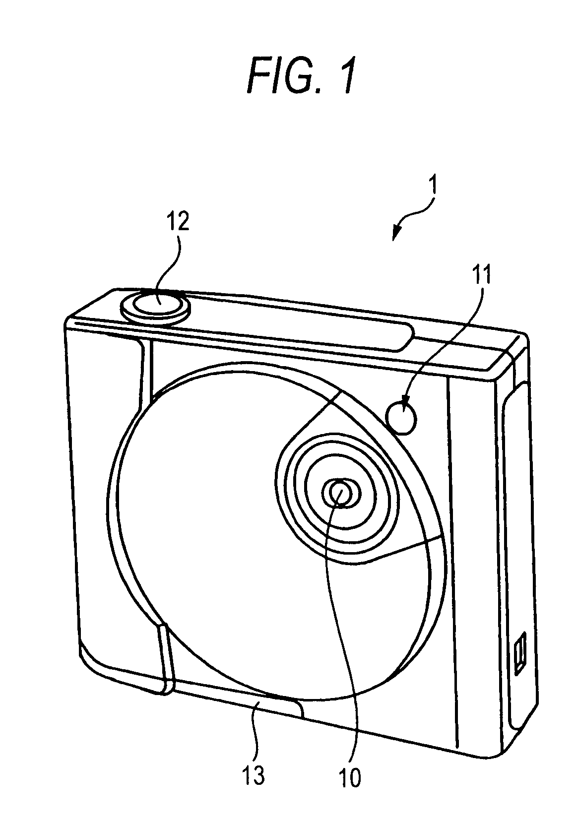
[0047]FIG. 1 is a perspective view illustrating, from obliquely above, an external appearance of a digital camera employing an embodiment of an image blurring correction unit according to the invention.

[0048]A digital camera shown in FIG. 1 is a compact autofocus camera on whic...


PUM


Abstract

An image blurring correction unit comprises: a holding module that holds a lens; a support member having a support portion that holds the holding module at an axial point so as to be swingable in an optional direction, the axial point being one point along an outer periphery of the holding module; and two drive mechanisms that drive the holding module through first and second drive points, which are apart from the axial point in first and second directions differing from each other, respectively, the two drive mechanisms comprising: a first drive mechanism that turns the holding module, through the first drive point, around a first axis connecting the axial point to the second drive point; and a second drive mechanism that turns the holding module, through the second drive point, around a second axis connecting the axial point to the first drive point, wherein the support member further comprises a first wing portion and a second wing portion that are interposed by the support portion and extend in the first direction and the second direction, respectively, and that hold the first drive mechanism and the second drive mechanism, respectively.

Description

BACKGROUND OF THE INVENTION[0001]1. Field of the Invention[0002]The present invention relates to an image blurring correction unit suitably for use as a camera shake correction in an imaging apparatus, for example, a digital camera and a camera-equipped cell-phone, an image blurring correction apparatus including the image blurring correction unit, and an imaging apparatus having the image blurring correction apparatus.[0003]2. Description of the Related Art[0004]Hitherto, digital cameras or the like have employed various camera shake correction mechanisms so as to prevent a disturbance of a photographed image from being caused by a user's hand trembling or the like (see JP-A-7-274056, JP-A-2005-326807 and Japanese Patent No. 2612371).[0005]Some of such camera shake correction mechanisms have employed what is called a gimbal mechanism so that a holding module can turn in a pitching direction and in a yawing direction.[0006]However, in the case of the gimbal mechanism disclosed in JP...

Claims


Application Information

Patent Timeline
Patent Type & Authority Applications(United States)
IPC IPC(8): H04N5/228
CPCG02B13/001G02B13/0035G02B27/646G03B5/00G03B2205/0069H04N5/2254H04N5/23248H04N5/23258H04N5/23287G03B2205/0007H04N23/55H04N23/60H04N23/68H04N23/6812H04N23/687
Inventor SEKINO, SHIZUO
Owner FUJI PHOTO OPTICAL CO LTD
Why Eureka
Try Eureka