Display device

Active Publication Date: 2008-03-27
PANASONIC LIQUID CRYSTAL DISPLAY CO LTD +1
View PDF2 Cites 11 Cited by
  • Summary
  • Abstract
  • Description
  • Claims
  • Application Information

AI Technical Summary

Benefits of technology

[0023]The present invention realizes, in a transflective type liquid crystal display device, a display device where the occurrence of non-uniformities in the thickness of the second insulating film in the vicinities of the contact holes is reduced when the second insulating film is formed.
[0024]According to the present invention, it becomes possible to apply a second insulating film in a uniform film thickness on a first insulating film and form an insulating film with few non-uniformities in a display device disposed with reflective regions and transmissive regions.

Problems solved by technology

Further, concavo-convexities for scattering light are formed in the reflective regions, and when the pixel electrodes are formed on the reflective regions, the problem arises that irregularity also arise in the pixel electrodes because of the concavo-convexities.
In the attempt to planarize these concavo-convexities, the present inventor discovered a problem in that, when the second organic resin film is applied to the first organic resin film, the film thickness of the second organic resin film does not become uniform and radial non-uniformities occur depending on the shape of the first organic resin film.

Method used


Image

  • Display device
  • Display device
  • Display device

Examples


Embodiment Construction

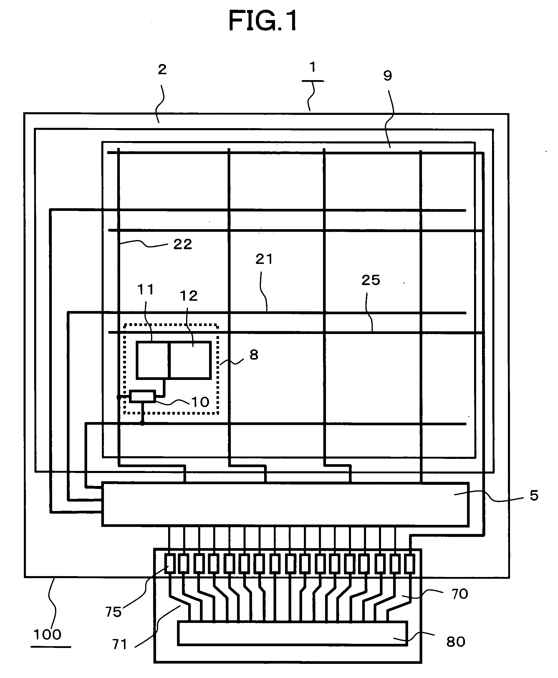
[0054]FIG. 1 is a plan schematic diagram showing a liquid crystal display device 100 according to the present invention. The liquid crystal display device 100 is configured by a liquid crystal panel 1 and a control circuit 80. Signals needed for the display of the liquid crystal panel 1 are supplied from the control circuit 80. The control circuit 80 is mounted on a flexible substrate 70, and the signals are transmitted to the liquid crystal panel 1 via wires 71 and terminals 75.

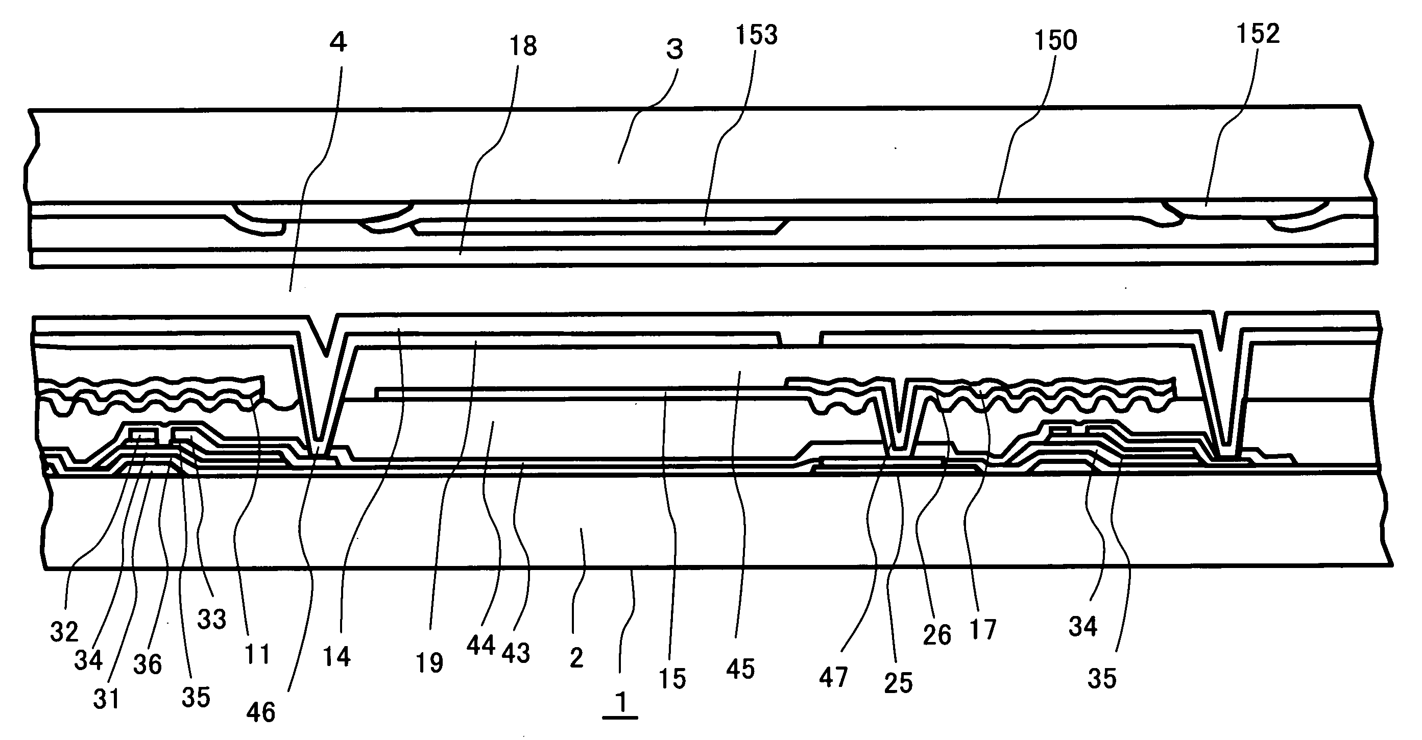
[0055]A reflective region 11 and a transmissive region 12 are disposed in each pixel portion 8 of the liquid crystal panel 1. It will be noted that although the liquid crystal panel 1 is disposed with a large number of the pixel portions 8 in a matrix, just one pixel portion 8 is shown in FIG. 1 in order to facilitate understanding. The pixel portions 8 arranged in a matrix form a display region 9, with each of the pixel portions 8 fulfilling the role of a pixel of an image, and display an image in the displ...


PUM


Abstract

In a liquid crystal display device disposed with reflective regions and transmissive regions, two organic insulating films are formed on a connection terminal portion and radial non-uniformities are prevented from occurring when applying the upper organic insulating film. Pixel portions including transmissive regions and reflective regions are formed, and a second organic insulating film is formed between a metal layer that forms reflective electrodes and a transparent conductive film that forms pixel electrodes to planarize concavo-convexities in the reflective electrodes. In contact holes of a connection terminal portion, the inclination of a first organic resin film is made smooth to control the occurrence of radial non-uniformities occurring in the second organic insulating film.

Description

BACKGROUND OF THE INVENTION[0001]1. Field of the Invention[0002]The present invention relates to a display device and in particular to a transflective type liquid crystal display device disposed with a conductive film on two insulating films.[0003]2. Background Art[0004]In recent years, so-called transflective type liquid crystal display devices disposed with the two display systems of a reflective display and a transmissive display have been heavily used as display units in portable devices, for example.[0005]Transflective type liquid crystal display devices are disposed with a transmissive region and a reflective region in a single pixel. In a transflective type display, a transmissive mode and a reflective mode are mixed. In the transmissive mode, light passes through the transmissive region disposed in the pixel and reaches the eyes of the viewer. In the reflective mode, light is reflected by the reflective region and reaches the eyes of the viewer.[0006]These transflective type...

Claims


Application Information

Patent Timeline
IPC IPC(8): G02F1/1335G02F1/1333
CPCG02F1/133345G02F2001/133357G02F1/13452G02F1/133555G02F1/133357
Inventor TANABE, HIDEOTAKABATAKE, MASARUNAKATSUKA, HIDEAKIKANEKO, TOSHIKI
Owner PANASONIC LIQUID CRYSTAL DISPLAY CO LTD
Why Eureka
Try Eureka