Plasma generating device

Inactive Publication Date: 2008-11-06
DELTA ELECTRONICS INC
View PDF5 Cites 8 Cited by
  • Summary
  • Abstract
  • Description
  • Claims
  • Application Information

AI Technical Summary

Benefits of technology

[0010]It is a fifth aspect of the present invention to provide a plasma generating device for generating a plasma with a uniform intensity, the plasma generating device comprises a first antenna to transmit the first electromagnetic wave, and a second antenna to transmit the second electromagnetic wave, wherein the first electromagnetic wave and the se

Problems solved by technology

Consequently, it's difficult to make the plasma source with a large uniform area.
Despite the advanced technologies provided in the prior art, it is found that the uniformity of the microwave plasma with the large area is still an issue.

Method used


Image

  • Plasma generating device
  • Plasma generating device
  • Plasma generating device

Examples


Embodiment Construction

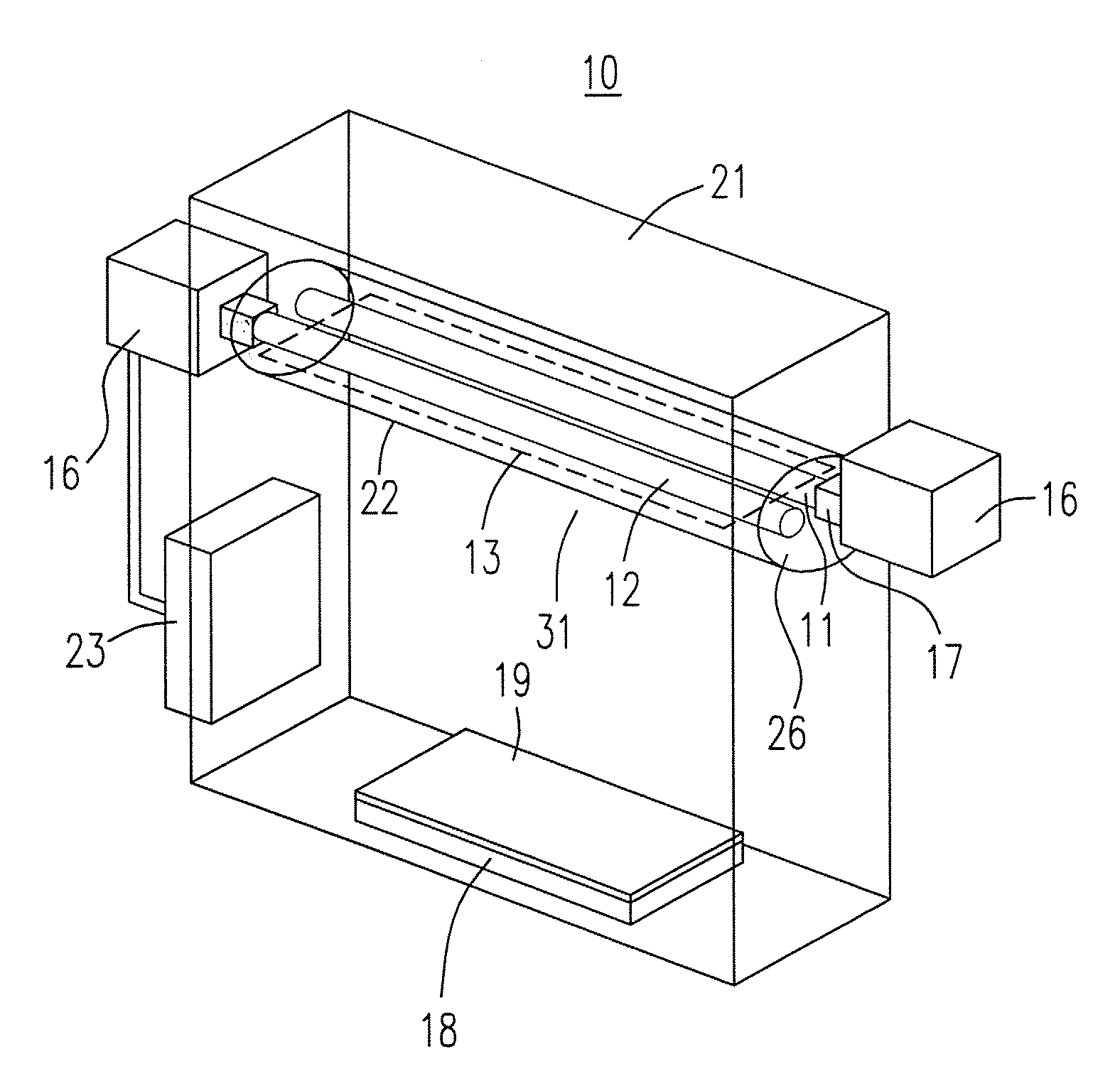
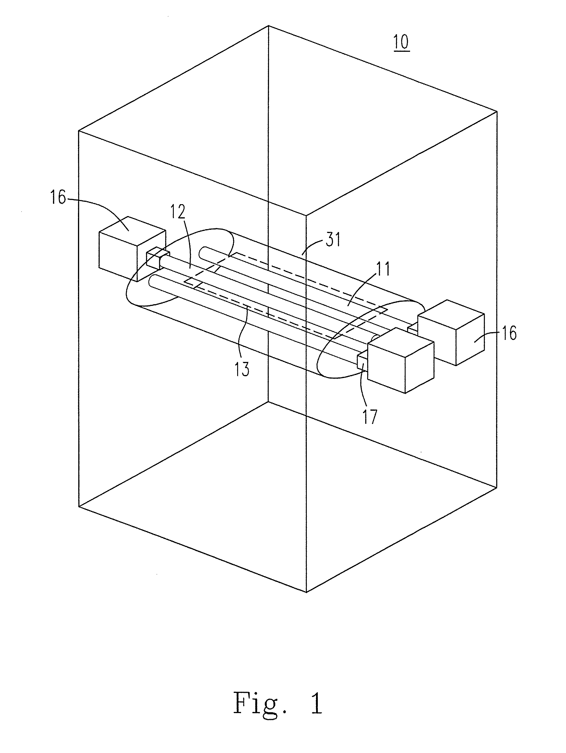
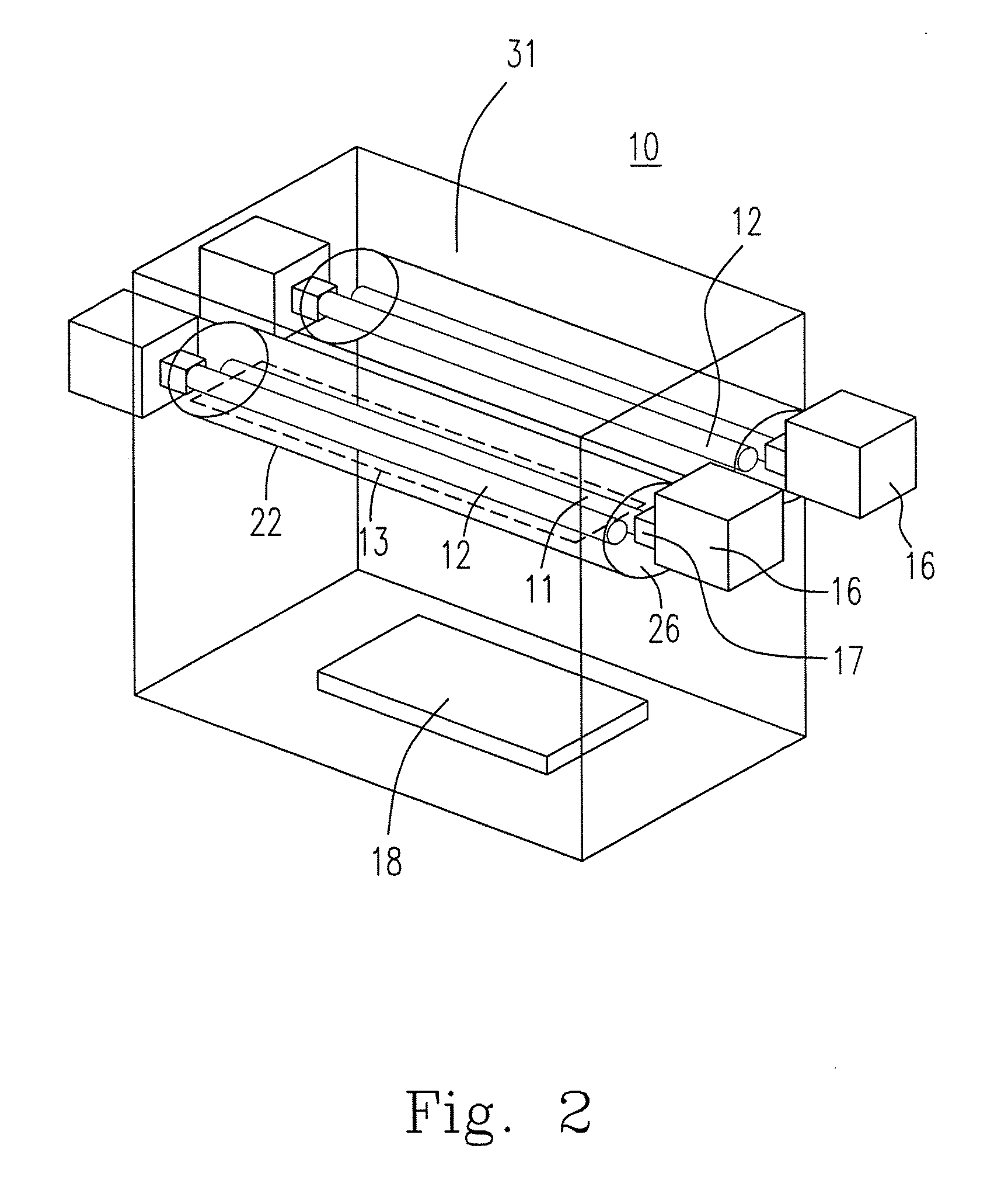
[0019]Please refer to FIG. 1, which is the plasma generating device according to a preferred embodiment in the present invention. The plasma generating device 10 includes an antenna module 31 for generating a plasma, wherein the antenna module 31 includes a first antenna 11 for transmitting a first electromagnetic wave and a second antenna 12 for transmitting a second electromagnetic wave, wherein the first antenna has an opposite orientation with respect to the second antenna, so that the first electromagnetic wave and the second electromagnetic wave are transmitted in opposite directions. Furthermore, the first and the second electromagnetic waves are supplied from electromagnetic wave generators 16 and input into the first antenna 11 and the second antenna 12 through electromagnetic wave couplers 17, respectively. Additionally, the first antenna 11 and the second antenna 12 are configured in the way that they are of the same length and parallel to each other with a distance there...


PUM


Abstract

In the present invention, a plasma generating device is provided for generating a plasma with a uniform intensity. The plasma generating device comprises at least a first antenna to transmit the first electromagnetic wave, at least a second antenna to transmit the second electromagnetic wave, and an insulator defining an isolated space for containing therein the first antenna and the second antenna, wherein the first antenna has an opposite orientation with respect to the second antenna, so that the first electromagnetic wave and the second electromagnetic wave are transmitted in opposite directions. The first and the second electromagnetic waves can be coupled with each other to produce a uniform standing wave pattern. Consequently, a large size uniform plasma can be generated.

Description

FIELD OF THE INVENTION[0001]The present invention relates to a plasma generating device. More particularly, the present invention relates to a plasma generating device utilizing electromagnetic waves.BACKGROUND OF THE INVENTION[0002]Plasmas are widely applied in industry and have become major equipments for etching, ashing and deposition in the fabrication process of semiconductors and TFT-LCD. Additionally, the plasma is used to enhance the chemical vapor deposition process of the silicon nitride layer, the amorphous silicon layer, the microcrystalline layer, the silicon dioxide layer, the diamond layer, the diamond-like layer and the carbon nanotube. Besides, plasmas are also used for the surface processing process, like the rainproof and moisture release cloth.[0003]Plasmas can be excited by electrical powers with different frequencies, including the DC discharge, the low and medium radio frequency discharge, and microwave discharge technologies. The frequency used in the low and...

Claims


Application Information

Patent Timeline
IPC IPC(8): H05H1/00
CPCH01J37/3222H05H1/46
Inventor LIN, JUI-YUKOU, CHWUNG-SHANWANG, TENG-WEIPAN, YAN-RUCHANG, TZU-CHINGYU, CHIH-CHIEH
Owner DELTA ELECTRONICS INC
Why Eureka
Try Eureka