
Method for producing metal automotive part and metal automotive part

Active Publication Date: 2016-08-25
NTN CORP
View PDF1 Cites 2 Cited by
  • Summary
  • Abstract
  • Description
  • Claims
  • Application Information

AI Technical Summary

Benefits of technology

The present invention provides a method for coating metal automotive parts with a uniform film of paint using a convergent nozzle-shaped covering jig. The method prevents unnecessary deposition, spillage, and fat edge at the boundary between the painted and unpainted portions of the part. The result is a more commercially efficient and aesthetically pleasing process for producing automotive parts.

Problems solved by technology

Thus the above-described powder coating method has a problem that the powder is liable to stick to the portion to be uncoated.
Thus the above-described powder coating method has a problem that the corrosion resistance of the coating film deteriorates.
In the method of flowing the air directly to the gap between the masking jig and the work, it is difficult to completely prevent the paint from penetrating into the gap.
This method has a problem that the corrosion resistance of the coating film deteriorates owing to a decrease in the thickness of the coating film.
In the method of coating the metal automotive part formed by tempering the quenched automotive part such as the constant velocity universal joint and bake-curing the coating powder paint at the same time, the above-described coating method has a problem that the thickness of the coating film fluctuates because convex and concave portions are present on a paint-applied portion according to the configuration of the inside of an outer ring of the constant velocity universal joint.

Method used


Image

  • Method for producing metal automotive part and metal automotive part
  • Method for producing metal automotive part and metal automotive part
  • Method for producing metal automotive part and metal automotive part

Examples


Embodiment Construction

[0034]Examples of a columnar or cylindrical metal automotive part include an outer joint member constructing a constant velocity universal joint and an intermediate shaft constructing a drive shaft.

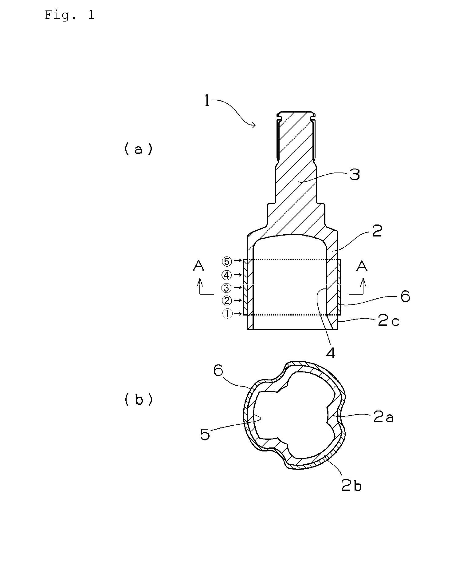
[0035]Carbon steel for machine structural use is molded by carrying out a forging method and thereafter the carbon steel for machine structural use is quenched and tempered to produce these metal automotive parts. The outer surfaces of the metal automotive parts are coated with paint to prevent them from rusting. Work hardening caused by forging, thermal stress caused by quenching, and quenching distortion caused by transformation stress are generated on the surfaces of the parts. Further, heating causes the parts to generate a plurality of iron oxides different from one another in oxidation states thereof on the surfaces thereof. Therefore the outer surfaces of the parts are not chemically and physically uniform as the surfaces to be coated with powder paint, but make it difficult to imp...


PUM


Abstract

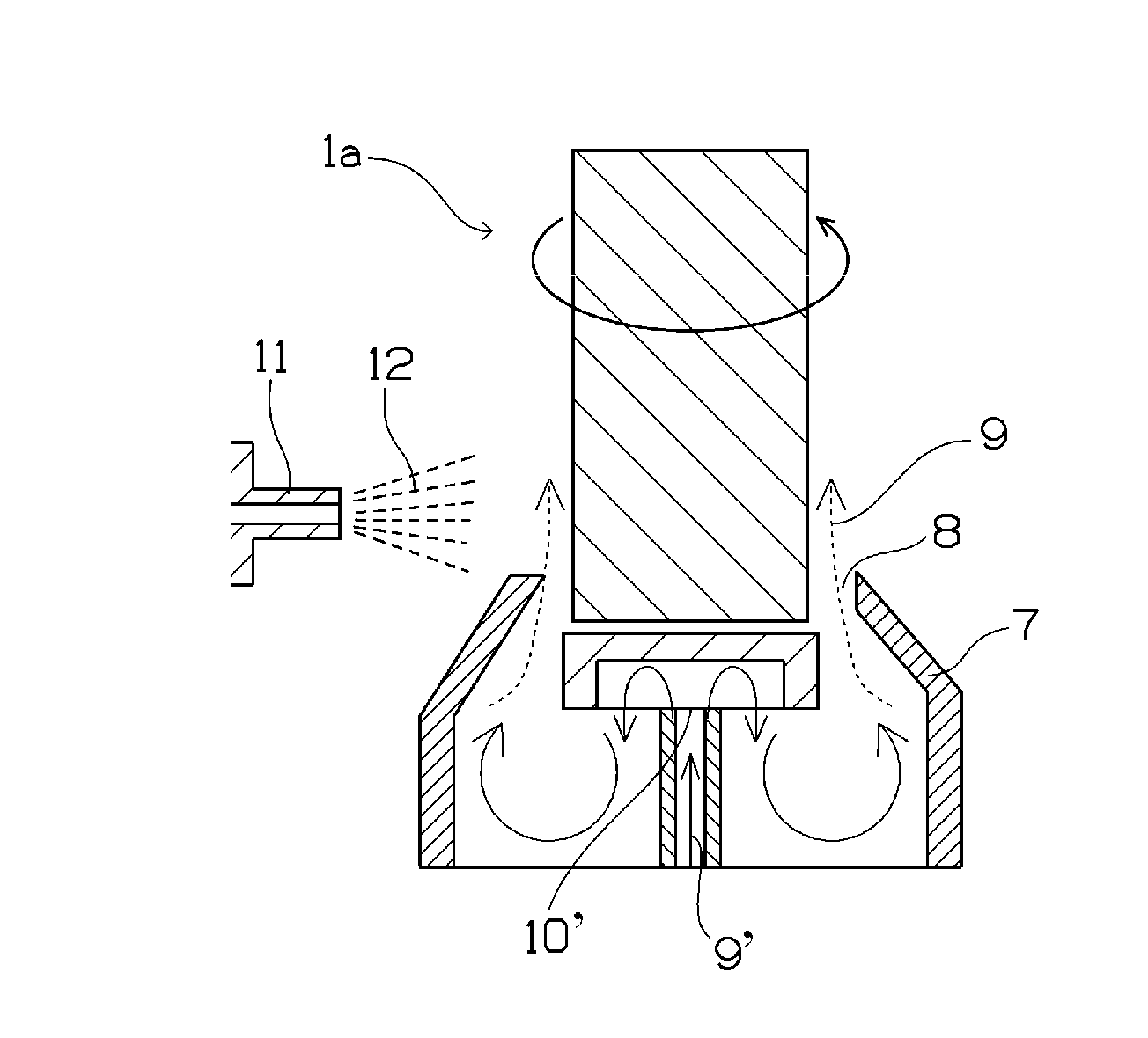
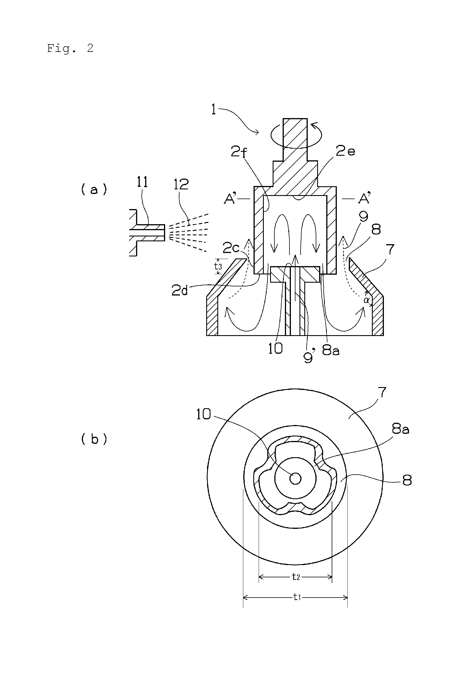
It is an object of the present invention to provide a method for uniformly forming a film on an outer circumferential portion of a metal automotive part by preventing penetration of a coating substance into a portion thereof unnecessary to be coated with paint. The method for producing a columnar or cylindrical metal automotive part whose outer circumferential surface includes a portion to be coated with paint and a portion to be uncoated therewith includes the following processes: (1) a process of providing a convergent nozzle-shaped covering jig which covers an outer circumferential surface of the columnar or cylindrical part at an axial end thereof and covers the portion to be uncoated with the paint, with a gap formed between the covering jig and the outer circumferential surface of the part; (2) a process of discharging a gas from the gap toward an end of a nozzle of the covering jig with the columnar or cylindrical part being rotated; (3) a process of sticking a film-forming substance to the columnar or cylindrical part from an axial side surface thereof.

Description

TECHNICAL FIELD[0001]The present invention relates to a method for producing a metal automotive part and more particularly to masking in a powder coating method to be carried out for a columnar or tubular metal automotive part.BACKGROUND ART[0002]The powder coating method is utilized in many fields such as automobile parts, steel tubes, home appliances, household goods, and the like. The powder coating method is carried out to apply powder mainly to a flat surface of an exterior portion having a large area. In many cases, the powder coating method is used to apply the powder to the entire surface of an object to be coated (hereinafter referred to as work). But there is a case in which the work has a portion to be uncoated on its surface. In that case, it is necessary to mask the surface to be uncoated. As normal masking methods, a masking tape and a cap are widely used. In that case, it is necessary for an operator to manually perform these methods. As a method of automating an oper...

Claims


Application Information

Patent Timeline
IPC IPC(8): B05D1/12B05D1/00F16D3/16B05B5/00
CPCB05B5/00B05D1/32F16D3/2055F16D2300/12B05D1/002F16D2200/0082B05D1/12F16D3/16F16D2200/0021F16D2200/0056B05D1/02B05B13/0228B05B12/18B05B12/20B05B5/032B05B5/03
Inventor HAYASHI, HIROMISUZUKI, SHINTARONISHIO, TOSHIHIRO
Owner NTN CORP
Learn More