
Method and apparatus for applying codes having pre-defined properties

a pre-defined property and code technology, applied in the field of applying codes, can solve the problems of limiting the performance of systems that use continuous sinusoidal waveforms, limiting the ability to address correlation and spectral property requirements, and using very little power to generate noise-like communication signals

Inactive Publication Date: 2008-03-27
HUMATICS CORP
View PDF36 Cites 87 Cited by
  • Summary
  • Abstract
  • Description
  • Claims
  • Application Information

AI Technical Summary

Benefits of technology

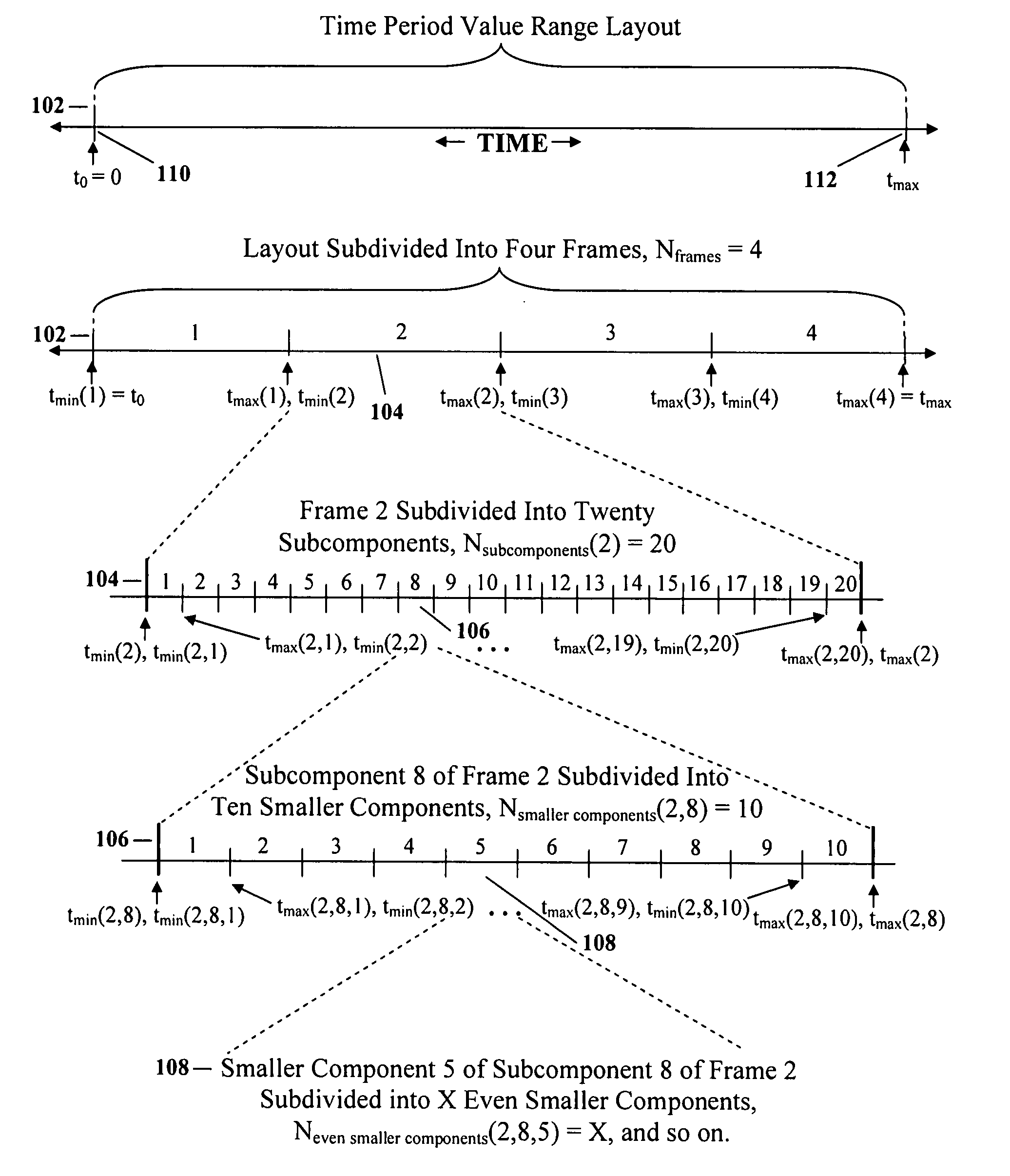
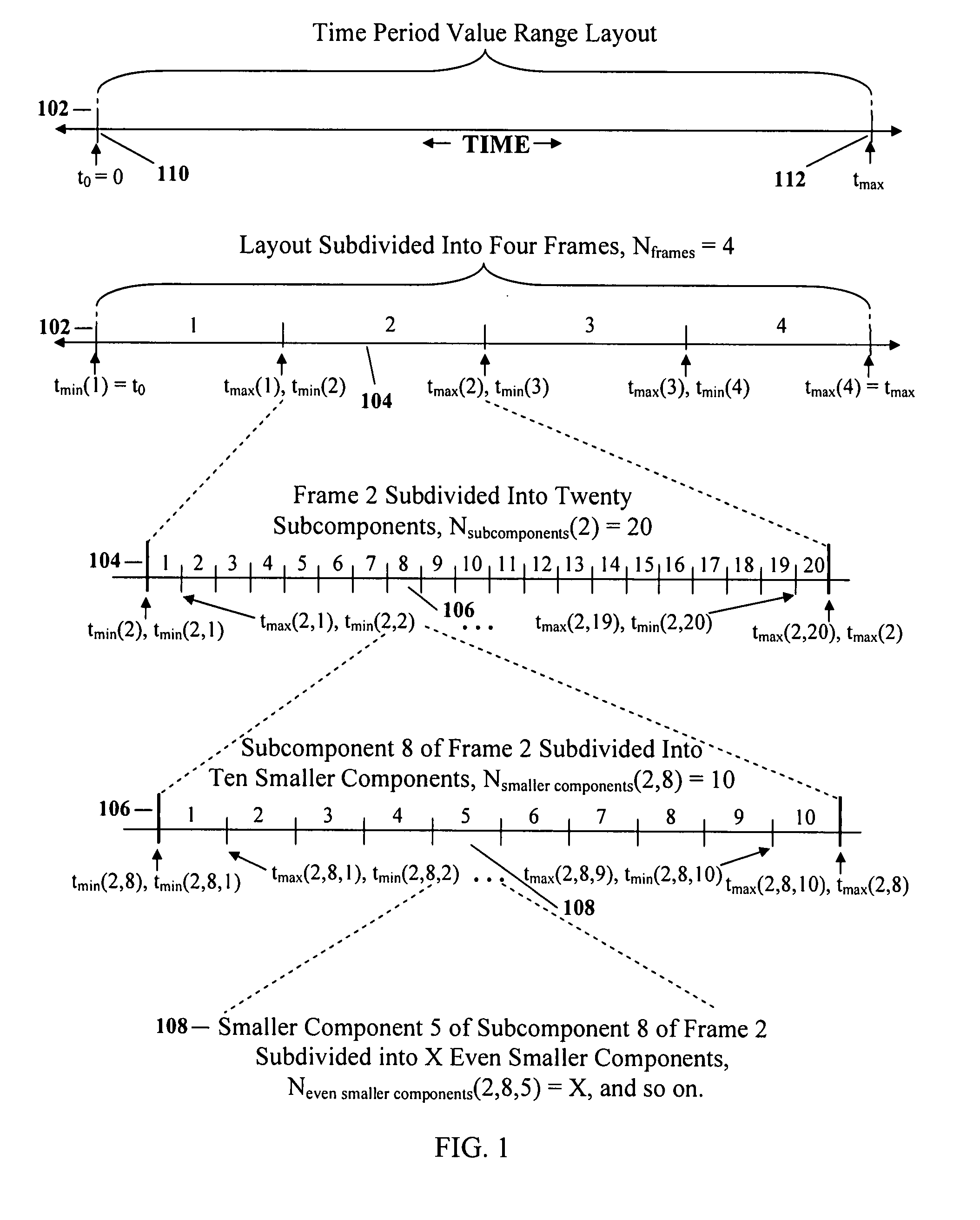
[0026] Briefly, according to the present invention, a sequential and/or nested combination of two or more codes is used to specify pulse characteristics, e.g., pulse time positions, such that the correlation and/or spectral properties of the combined codes are realized. The present invention provides a method for specifying pulse characteristics that specifies a layout that is subdivided into at least a first and a second component. The present invention applies a first code having first pre-defined properties to the first component, and applies a second code having second pre-defined properties to the second component

Problems solved by technology

As a result, the impulse radio transmitter uses very little power to generate noise-like communication signals for use in multiple-access communications, radar and positioning applications, among other things.
Because of the extremely high achievable processing gains, the impulse radio systems are relatively immune to unwanted signals and interference, which limit the performance of systems that use continuous sinusoidal waveforms.
The described time-hopping code methods produce codes that can be employed to address either a spectral property requirement or a correlation property requirement of given application, but are limited in their ability to address both correlation and spectral property requirements.
As a result, such codes are limited in their ability to address both signal acquisition and channelization requirements of a given TM-UWB application requiring tradeoffs to be made when selecting a time-hopping code.

Method used


Image

  • Method and apparatus for applying codes having pre-defined properties
  • Method and apparatus for applying codes having pre-defined properties
  • Method and apparatus for applying codes having pre-defined properties

Examples


Embodiment Construction

I. Introduction

[0054] The present invention provides a method of using a combination of two or more generated codes to specify characteristics of pulses within a pulse train, e.g., time positions. Usually, each generated code consists of a set or a number of code element values. The method involves defining one or more characteristic value layouts, generating two or more codes with pre-defined properties, and mapping the codes to the characteristic value layout(s). In one exemplary embodiment a combination of codes are mapped to sequential layouts. In another embodiment a combination of codes are nested such that one code specifies subcomponents within a layout while the second code specifies discrete values within the subcomponents specified by the first code. In another embodiment a combination of nested codes are mapped to sequential layouts.

[0055] The detailed description that follows describes the use of the present invention to specify a pulse time position characteristic. Ho...


PUM


Abstract

A method for specifying pulse characteristics applies codes having pre-defined characteristics to a layout. The layout can be sequentially subdivided into at least first and second components that have the same or different sizes. The method applies a first code having first pre-defined properties to the first component and a second code having second pre-defined properties to the second component. The pre-defined properties may relate to the auto-correlation property, the cross-correlation property, and spectral properties, as examples. The codes can be used to specify subcomponents within a frame, and characteristic values (range-based, or discrete) within the subcomponents.

Description

CROSS-REFERENCE TO OTHER APPLICATIONS [0001] This application is a continuation of U.S. patent application Ser. No. 09 / 638,192, filed Aug. 15, 2000, which is a continuation-in-part of U.S. patent application Ser. No. 09 / 592,250, filed Jun. 12, 2000, now abandoned. [0002] The following applications of common assignee may contain common disclosure with the present application: [0003] U.S. patent application Ser. No. 09 / 638,192, entitled “A METHOD FOR SPECIFYING NON-TEMPORAL PULSE CHARACTERISTICS”, filed Aug. 15, 2000, currently pending. [0004] U.S. patent application Ser. No. 09 / 637,878, entitled “A METHOD AND APPARATUS FOR POSITIONING PULSES USING A LAYOUT HAVING NON-ALLOWABLE REGIONS”, filed Aug. 15, 2000, now abandoned. [0005] U.S. patent application Ser. No. 09 / 638,510, entitled “A METHOD AND APPARATUS FOR POSITIONING PULSES IN TIME”, filed Aug. 15, 2000, issued Oct. 25, 2005 as U.S. Pat. No. 6,959,032. [0006] U.S. patent application Ser. No. 09 / 638,151, entitled “A METHOD AND APP...

Claims


Application Information

Patent Timeline
IPC IPC(8): H04B1/38H04L25/49
CPCH04L25/4902
Inventor ROBERTS, MARK D.PENDERGRASS, MARCUS H.FULLERTON, LARRY W.COWIE, IVAN A.RICHARDS, JAMES L.
Owner HUMATICS CORP
Learn More