Composite turbomachine blade with metal reinforcement

a turbomachine blade and metal reinforcement technology, which is applied in the direction of machines/engines, liquid fuel engines, other domestic articles, etc., can solve the problems that the structural reinforcement of metal covering the leading edge of the blade is not always effective in protecting the set of composite blades

Active Publication Date: 2008-03-27
SN DETUDE & DE CONSTR DE MOTEURS DAVIATION S N E C M A
View PDF8 Cites 61 Cited by
  • Summary
  • Abstract
  • Description
  • Claims
  • Application Information

AI Technical Summary

Benefits of technology

[0005]A main aim of the present invention is thus to mitigate such a drawback by proposing a composite blade capable of withstanding the impact from a foreign body without leading to degradation of the set of composite blades.

Problems solved by technology

Nevertheless, the presence of structural reinforcement made of metal covering the leading edge of the blade is not always effective in protecting the set of composite blades in the event of an impact from a foreign body.

Method used


Image

  • Composite turbomachine blade with metal reinforcement
  • Composite turbomachine blade with metal reinforcement
  • Composite turbomachine blade with metal reinforcement

Examples


Embodiment Construction

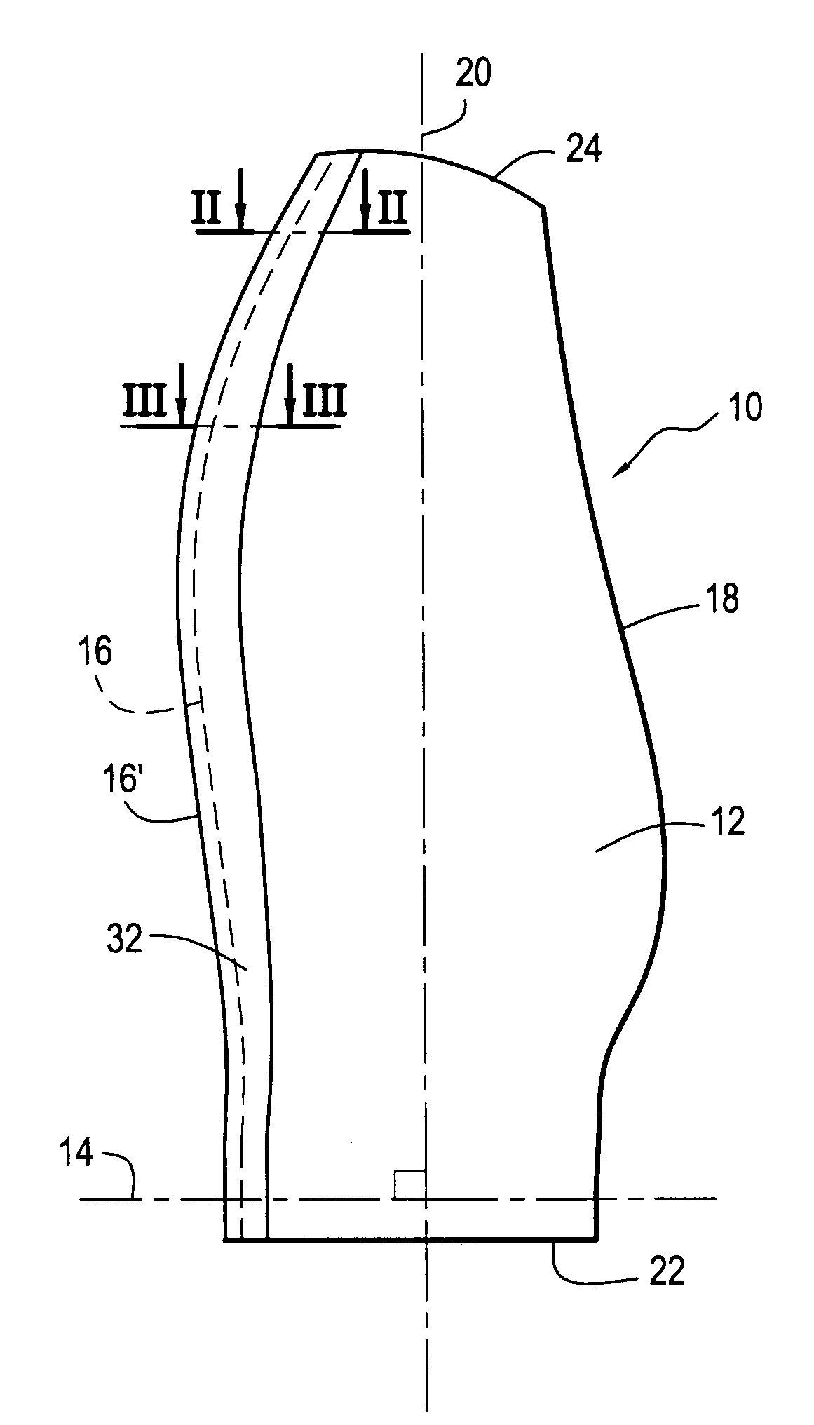
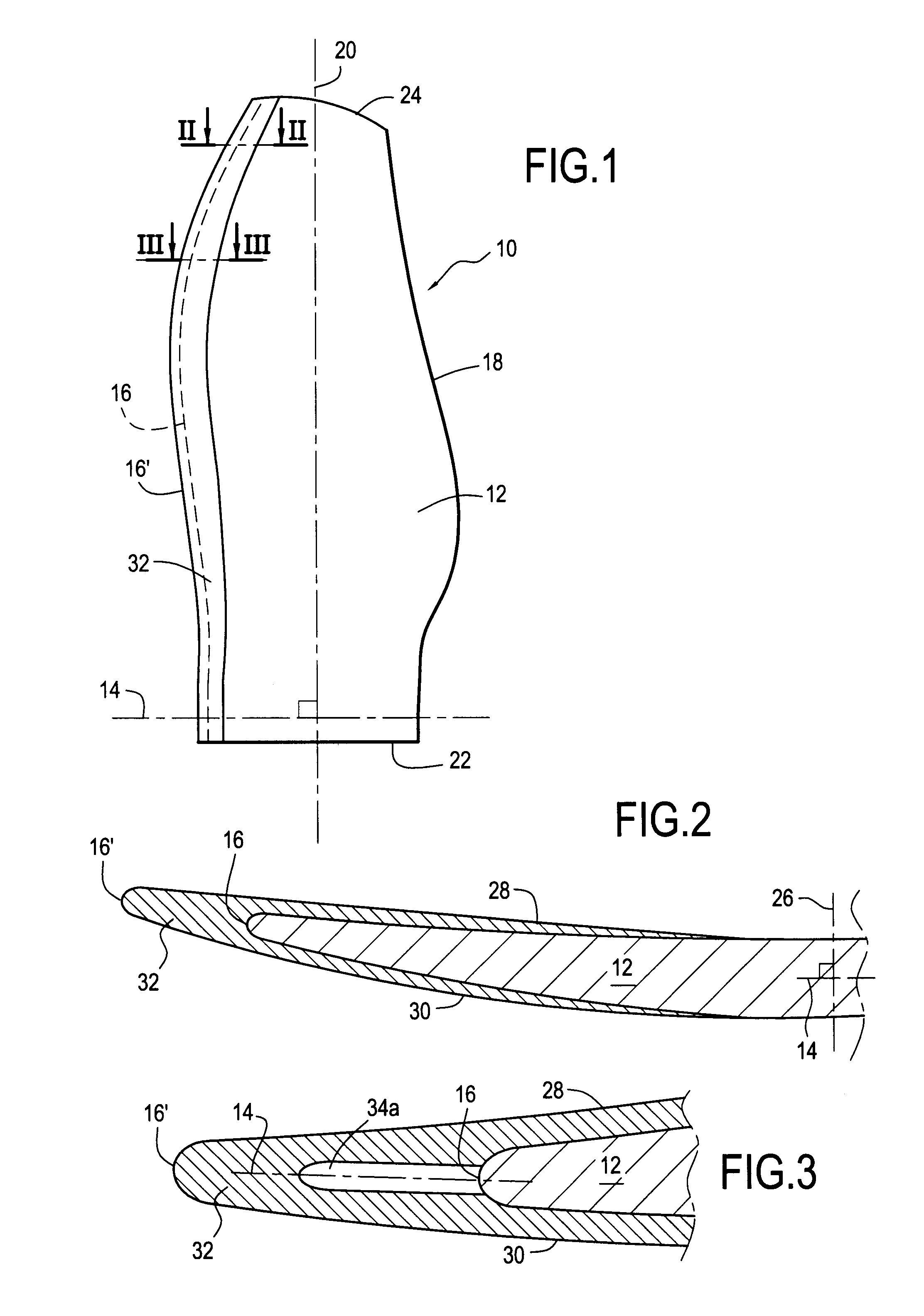
[0019]FIGS. 1 to 3 show a turbomachine blade 10 constituting an embodiment of the invention. By way of example, the blade is a moving blade of a turbomachine fan.

[0020]The blade presents an aerodynamic surface 12 extending in an axial first direction 14 between a leading edge 16 and a trailing edge 18, and in a radial second direction 20 that is substantially perpendicular to the first direction 14 between a root 22 and a tip 24. As shown in FIG. 2, which shows a portion of the blade in cross-section, the blade also extends in a tangential third direction 26 perpendicular to the first and second directions between a pressure side 28 and a suction side 30. The pressure side and the suction side of the blade form its side faces interconnecting the leading edge 16 and the trailing edge 18 of the blade.

[0021]The blade, and more particularly its aerodynamic surface 12 as defined above, is obtained by draping or weaving a composite material. By way of example, the composite material may b...


PUM

PropertyMeasurementUnit
distanceaaaaaaaaaa
distanceaaaaaaaaaa
energyaaaaaaaaaa

Abstract

The invention relates to a turbomachine blade comprising an aerodynamic surface made of a composite material and extending in a first direction between a leading edge and a trailing edge, and in a second direction between a root and a tip of the blade. The blade includes solid metal reinforcement that is adhesively bonded to the leading edge of its aerodynamic surface, which reinforcement extends along the first direction beyond the leading edge of the aerodynamic surface and along the second direction between the root and the tip, and includes at least one recess for absorbing at least a portion of the energy that results from an impact of a foreign body against the leading edge of the blade.

Description

BACKGROUND OF THE INVENTION[0001]The present invention relates to the general field of turbomachine blades. It relates more particularly to a turbomachine fan blade made of composite material and having its leading edge fitted with structural reinforcement made of metal.[0002]It is known to fit the fan blades of a turbomachine that are made of composite material with structural reinforcement made of metal that extends over the full height of the blade and beyond its leading edge. Such reinforcement serves to protect the set of composite blades in the event of a foreign body impacting the fan, such as a bird being ingested by the turbomachine, for example.[0003]In particular, the metal reinforcement protects the leading edge of the composite material blade by preventing delamination if the blade is a draped blade, and damage by fiber / matrix decohesion or by fiber rupture if the blade is a woven blade.[0004]Nevertheless, the presence of structural reinforcement made of metal covering ...

Claims


Application Information

Patent Timeline
Patent Type & Authority Applications(United States)
IPC IPC(8): F01D5/14
CPCF01D5/147B29C65/48F04D29/023F04D29/324F04D29/388B29C66/53B29C66/12461B29C66/12463B29C66/301B29C66/721B29C66/742B29L2031/08B29L2031/082F05D2300/501F05D2300/506F05D2300/133B29C65/484F05D2240/303F05D2300/702F05D2230/23B29C65/483F01D5/282
Inventor GIUSTI, STEPHANE RENE JULIENJACQ, CHRISTOPHELOMBARD, JEAN-PIERRE FRANCOISSUFFIS, ARNAUD RENE
Owner SN DETUDE & DE CONSTR DE MOTEURS DAVIATION S N E C M A
Why Eureka
Try Eureka