Audio-signal processing apparatus and method
a processing apparatus and audiosignal technology, applied in the field of audiosignal processing apparatus and method, can solve problems such as degrading the reproducibility of musi
- Summary
- Abstract
- Description
- Claims
- Application Information
AI Technical Summary
Benefits of technology
Problems solved by technology
Method used
Image
Examples
first embodiment
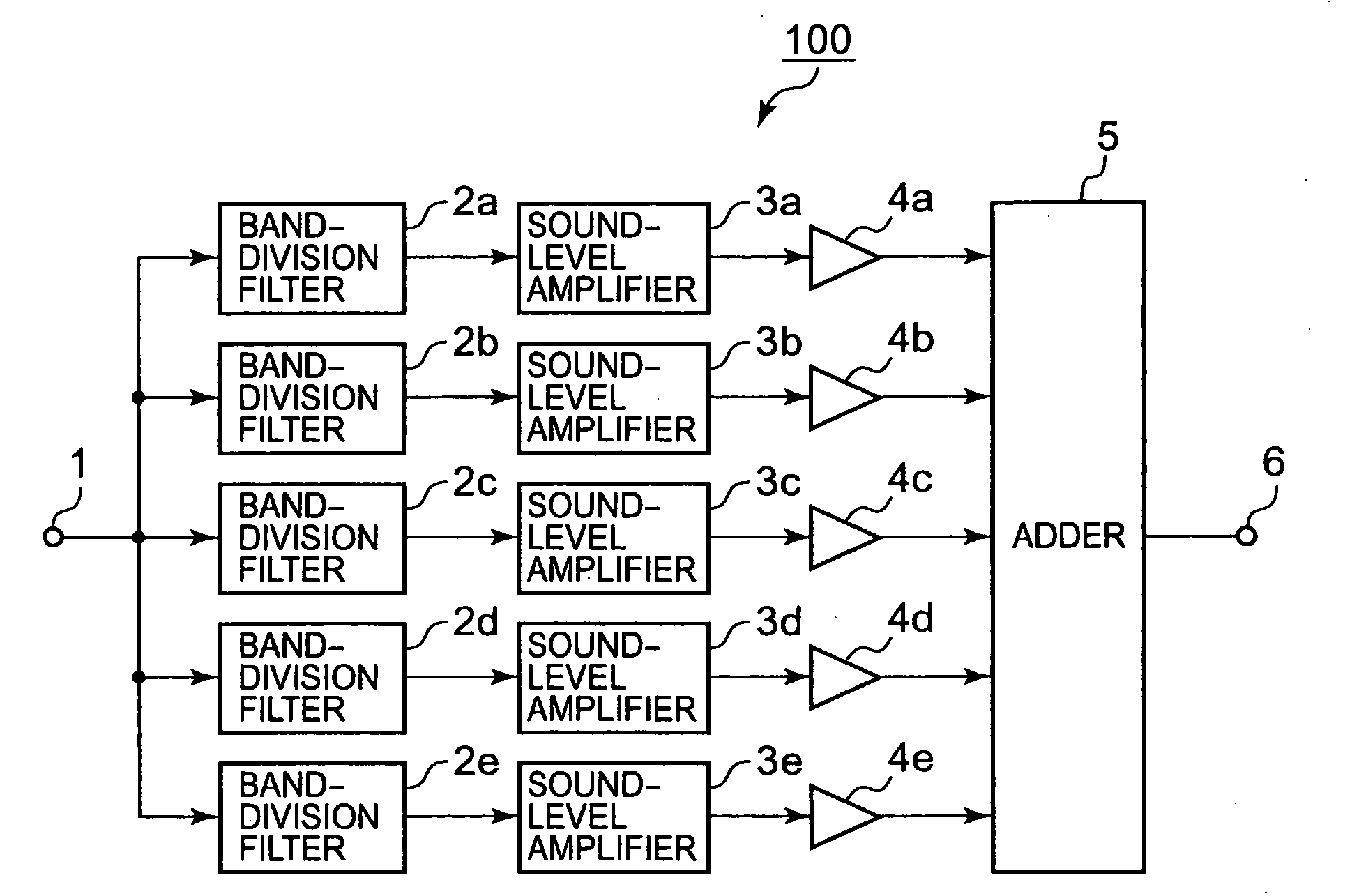
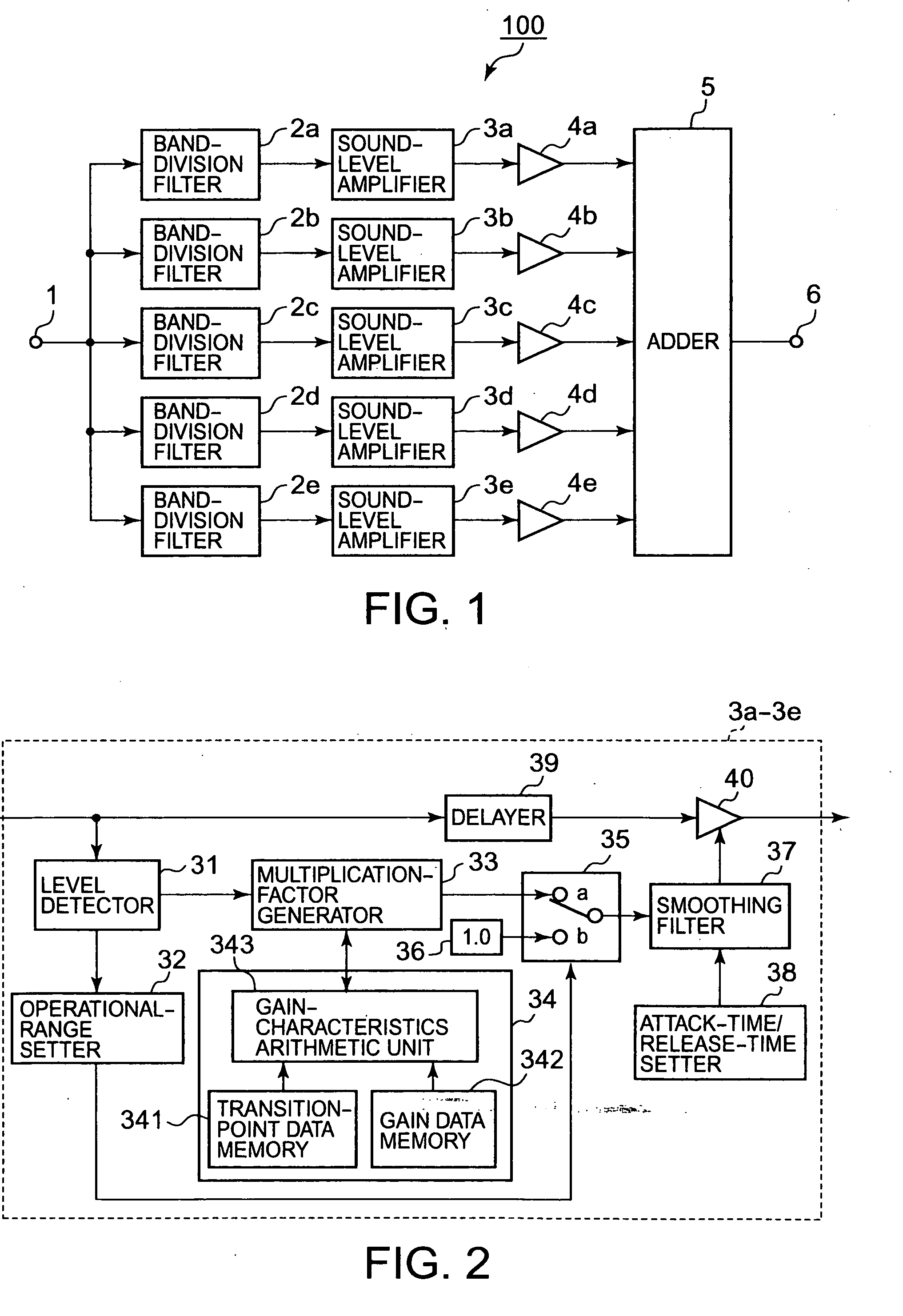
[0028]The block diagram shown in FIG. 1 represents a first embodiment of audio-signal processing apparatus. An audio-signal processing apparatus 100 shown in FIG. 1 has basic components essential for each embodiment.
[0029]In FIG. 1, a digital audio signal (a first audio signal) input via an input terminal 1 is supplied to band-division (band-pass) filters 2a to 2e with different frequency bands.
[0030]The frequency range for which human beings can hear is more or less 20 Hz to 20 kHz. In this range, the band-division filters 2a to 2e may, for example, be adjusted to allow the following bands to pass:
[0031]Filter 2a: a low frequency band such as from 20 Hz to 200 Hz;
[0032]Filter 2b: a low-to-intermediate frequency band such as from 200 Hz to 600 Hz;
[0033]Filter 2c: an intermediate frequency band such as from 600 Hz to 1.8 kHz;
[0034]Filter 2d: an intermediate-to-high frequency band such as from 1.8 kHz to 5.4 kHz; and
[0035]Filter 2e: a high frequency band such as from 5.4 kHz to 20 kHz...
second embodiment
[0102]The block diagram shown in FIG. 8 represents a second embodiment of audio-signal processing apparatus. In an audio-signal processing apparatus 200 shown in FIG. 8, the same reference numerals are given to the elements identical or analogous to those of the counterpart 100 shown in FIG. 1, the detailed explanation thereof being omitted.
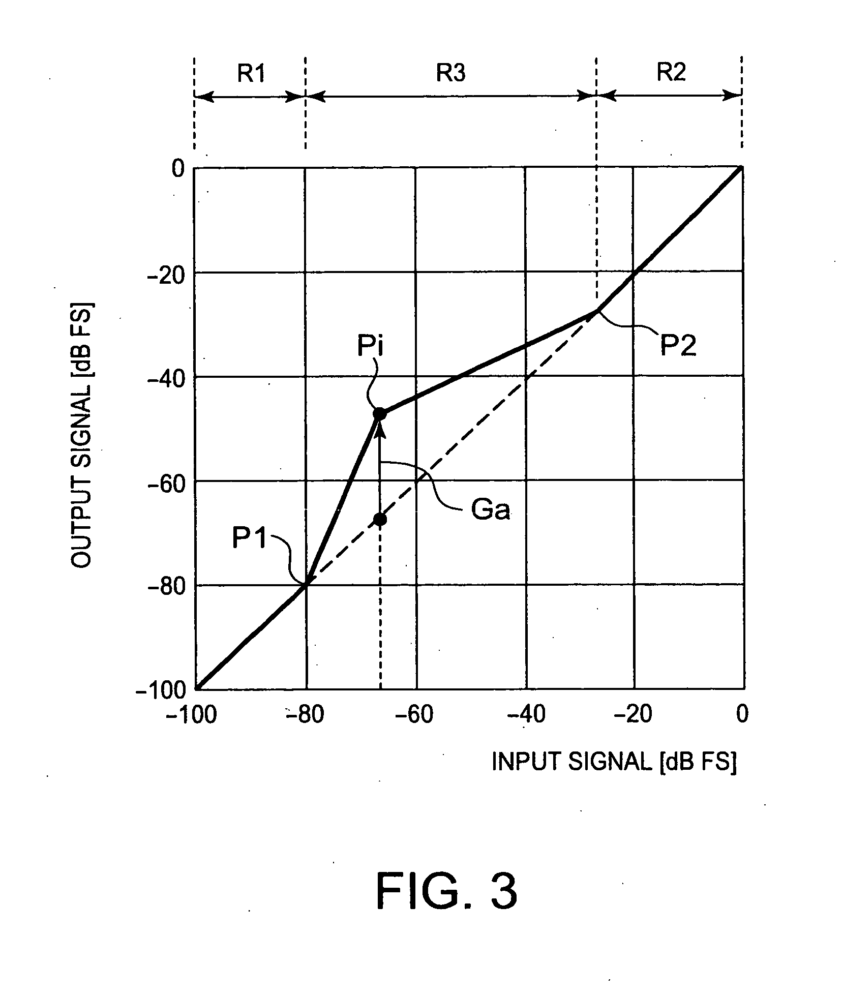
[0103]The audio-signal processing apparatus 200 features gain control in amplifying an audio signal at sound-level amplifiers 3a1 to 3e1 depending on the dynamic range of the audio signal. The gain to be controlled is the gain Ga at the transition point Pi (discussed in the first embodiment) set at a gain-characteristics setter 340 shown in FIG. 12, which will be described later.
[0104]In FIG. 8, a media reproducer 201 is a known optical-disc reproducer for use in optical-disc (CD, DVD, etc.) reproduction. A signal reproduced from an optical disc at the media reproducer 201 is supplied to a signal processor 202.
[0105]The signal processor 202 deter...
third embodiment
[0133]The block diagram shown in FIG. 13 represents a third embodiment of audio-signal processing apparatus. In an audio-signal processing apparatus 300 shown in FIG. 13, the same reference numerals are given to the elements identical or analogous to those of the counterpart 100 shown in FIG. 1 or the counterpart 200 shown in FIG. 8, the detailed explanation thereof being omitted.
[0134]The audio-signal processing apparatus 300 features gain control in amplifying an audio signal at the sound-level amplifiers 3a1 to 3e1, with the gain Ga set depending on the genres of the contents carried by audio signals.
[0135]The audio-signal processing apparatus 300 is equipped with a receiver 301 for receiving digital broadcast signals, as shown in FIG. 13.
[0136]A digital broadcast signal received by the receiver 301 is supplied to a signal processor 302. Extracted from the broadcast signal by the processor 302 are contents data involving video and audio signals, and auxiliary data added to the co...
PUM
 Abstract
Description
Claims
Application Information
 - R&D
- Intellectual Property
- Life Sciences
- Materials
- Tech Scout
- Unparalleled Data Quality
- Higher Quality Content
- 60% Fewer Hallucinations
Browse by: Latest US Patents, China's latest patents, Technical Efficacy Thesaurus, Application Domain, Technology Topic, Popular Technical Reports.
© 2025 PatSnap. All rights reserved.Legal|Privacy policy|Modern Slavery Act Transparency Statement|Sitemap|About US| Contact US: help@patsnap.com


