Vibration monitoring system for gas turbine engines

Active Publication Date: 2006-03-14
TRIUMPH ENGINE CONTROL SYST
View PDF8 Cites 31 Cited by
  • Summary
  • Abstract
  • Description
  • Claims
  • Application Information

AI Technical Summary

Benefits of technology

[0028]In a representative system, small accelerometers are used to sense vibration levels or amplitudes and the performance characteristics of these sensors are specifically defined and selected to work in symbiotic fashion with the interface filtering and electronics. Additionally, special signal processing or filtering/condi

Problems solved by technology

Machinery having massive rotating components, such as jet aircraft engines, may experience shaft, bearing, and/or gear failures.
In addition, these rotating components may become unbalanced and impose loads upon the bearings and engine housing well beyond acceptable specifications.
These problems may be a result of any variety of causes which include, manufacturing defects, design defects, wear, misuse, accidental damages and the like.
In the case of in-flight aircraft, failure of these engine components can lead to, not only engine loss, but a catastrophic loss of aircraft and crew.
Vibration amplitudes and

Method used


Image

  • Vibration monitoring system for gas turbine engines
  • Vibration monitoring system for gas turbine engines
  • Vibration monitoring system for gas turbine engines

Examples


Example

[0043]These and other features of the subject disclosure will become more readily apparent to those having ordinary skill in the art from the following detailed description of preferred embodiments.

DETAILED DESCRIPTION OF PREFERRED EMBODIMENTS

[0044]Although the vibration monitoring system described herein below is adapted for use in a rotary wing aircraft engine platform, the inventive aspects of this system can be applied to marine platforms (e.g. boat or ship), land platforms (e.g., automobile or tracked vehicle), or to fixed wing aircraft platforms. Additionally, the vibration monitoring system disclosed herein can be applied to machinery other than engines without departing from the inventive aspects disclosed herein.

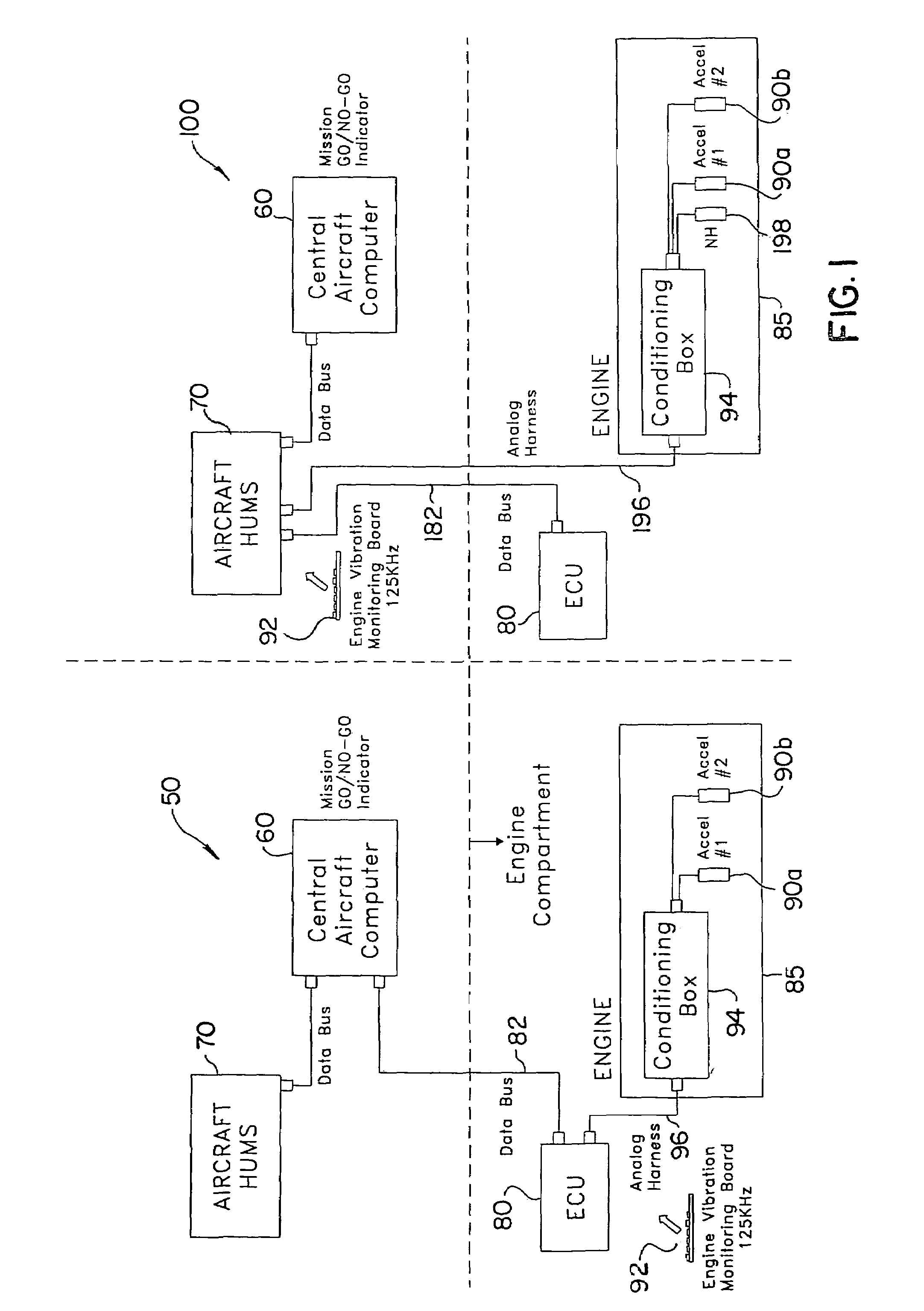
[0045]Referring now to the drawings there is illustrated in FIG. 1, two representative aircraft vibration monitoring system architectures, a Full Authority Digital Engine Control (FADEC) based system and a Heath and Usage Management (HUMS) based system, the systems ...


PUM


Abstract

Disclosed is a system and method for monitoring the vibration levels of gas turbine engines. The vibration monitoring system acquires vibration data from an engine, and processes the data with advanced algorithms to determine engine component health, both in a diagnostic and prognostic fashion. The method includes the steps of measuring an operating parameter and a corresponding set of vibration amplitudes for a plurality of rotating component during a period of operation and normalizing the set of measured vibration amplitudes based on established amplitude limits. The set of normalized amplitude data points are stored in parameter-based data blocks, which extend over a predetermined range of the operating parameter. For each data block, a time period remaining to reach the established amplitude limits is estimated based on changes in the normalized amplitude data points stored in the data blocks. An alarm setting is then established based on the estimated time period remaining to reach the established amplitude limits for each data block.

Description

CROSS REFERENCE TO RELATED APPLICATIONS[0001]This application is a continuation of U.S. patent application Ser. No. 10 / 295,528, filed Nov. 15, 2002, now U.S. Pat. No. 6,768,938 which claims priority to U.S. Provisional Patent Application Ser. No. 60 / 332,892, filed Nov. 16, 2001, entitled “Vibration Monitoring System for Gas Turbine Engines,” both of which are herein incorporated by reference in thier entirety.GOVERNMENT RIGHTS STATEMENT[0002]The U.S. Government has a paid-up license in this invention and the right in limited circumstances to require the patent owner to license others on reasonable terms as provided for by the terms of DAAH10-99-2-0005, awarded by the U.S. Department of the Army.BACKGROUND OF THE INVENTION[0003]1. Field of the Invention[0004]The subject disclosure relates to a control system for use with aircraft gas turbine engines, and more particularly to, a control system that includes a real-time vibration monitoring system having a diagnostic and a prognostic c...

Claims


Application Information

Patent Timeline
IPC IPC(8): G01H1/00G06F17/00
CPCG01H1/006
Inventor MCBRIEN, GARY M.GOTTWALD, JAMES
Owner TRIUMPH ENGINE CONTROL SYST
Why Eureka
Try Eureka