Shaker and degasser combination

a shaker and degasser technology, applied in the direction of filtration separation, separation process, borehole/well accessories, etc., can solve the problems of time-consuming and expensive mud evaluation and mixture process, too light may not protect, and too heavy may over-invade the formation

Active Publication Date: 2008-04-03
MI
View PDF12 Cites 110 Cited by
  • Summary
  • Abstract
  • Description
  • Claims
  • Application Information

AI Technical Summary

Problems solved by technology

Drilling mud that is too light may not protect the formation from blow outs, and drilling mud that is too heavy may over invade the formation.
Because the mud evaluation and mixture process is time consuming and expensive, drillers and service companies prefer to reclaim the returned drilling mud and recycle it for continued use.
The frame of the vibrating screen is resiliently suspended or mounted upon a support and is caused to vibrate by a vibrating mechanism (e.g., an u

Method used


Image

  • Shaker and degasser combination
  • Shaker and degasser combination
  • Shaker and degasser combination

Examples


Embodiment Construction

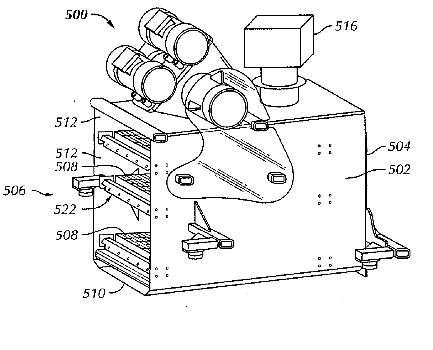
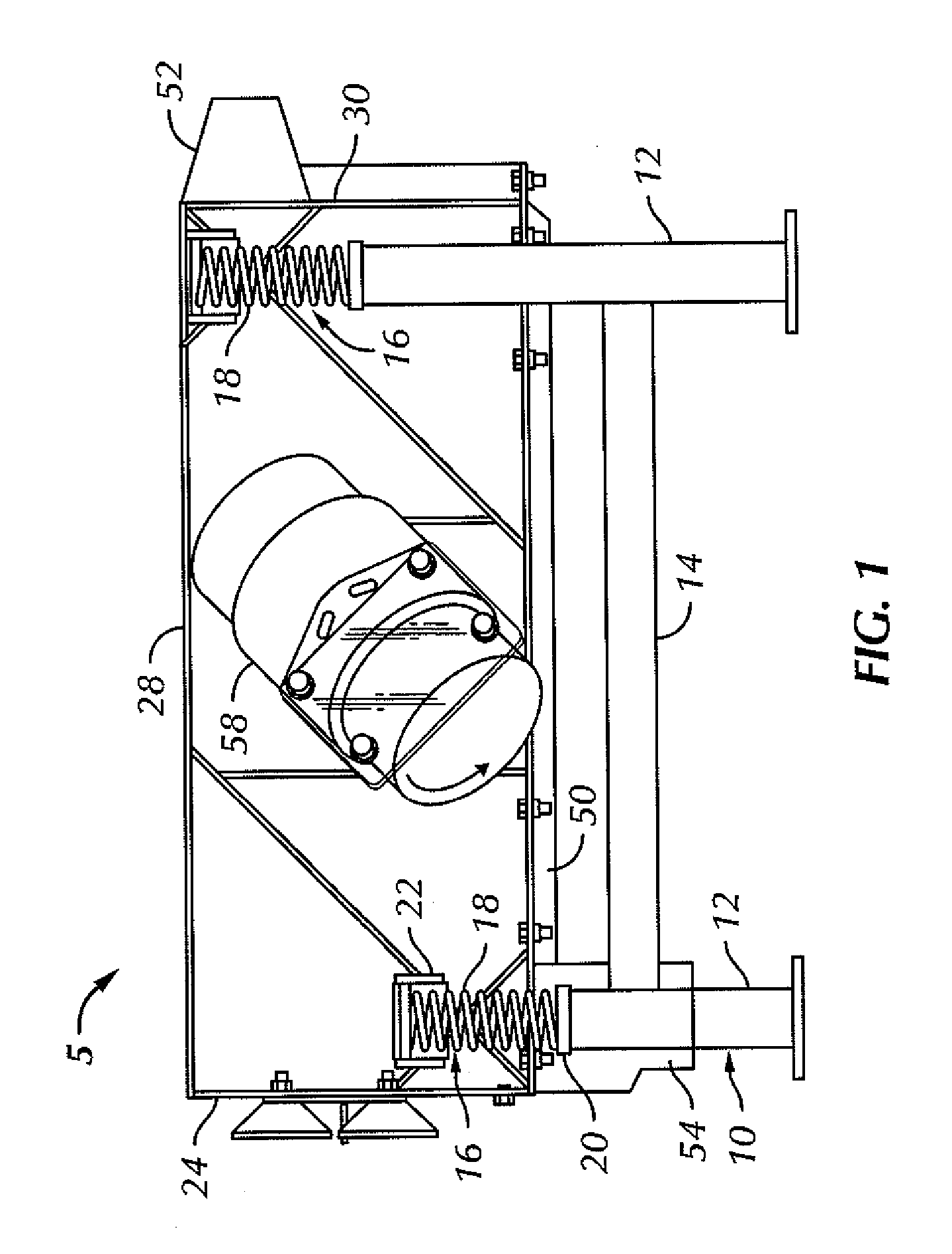
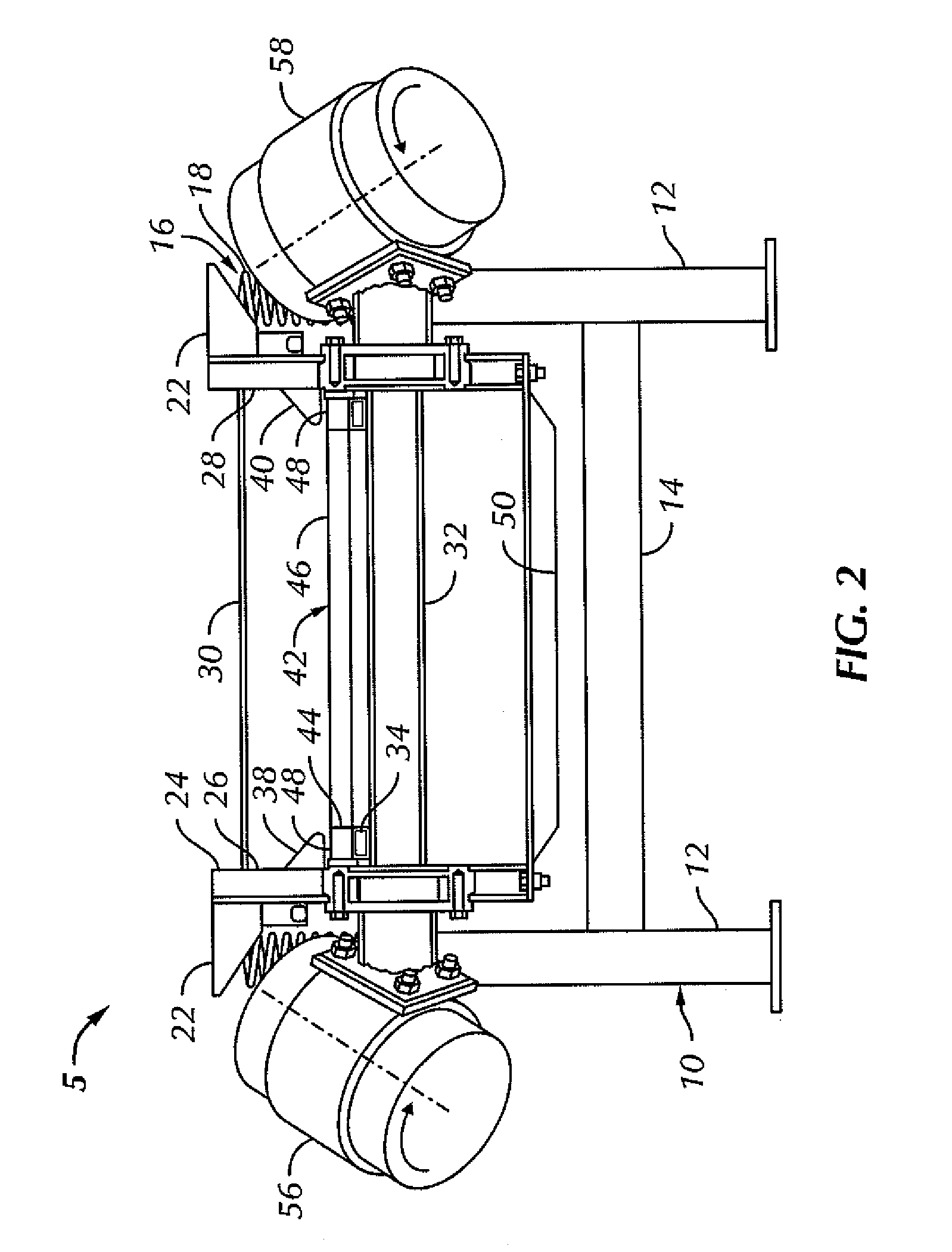
[0027] In one aspect, embodiments disclosed herein relate to a method for separating components of a slurry. As used herein, a slurry refers to a mixture of drilling fluid and drill cuttings. A slurry may be separated using a screen separator having a pressure differential across the screen. In other aspects, embodiments disclosed herein relate to a system for separating components of a slurry. The system may include, in some embodiments, a vibratory screen separator and a pressure differential device or a vacuum generating device. The pressure differential device may additionally provide a driving force to degas the recovered drilling fluid.

[0028]FIGS. 1 and 2 illustrate one embodiment of a vibratory screen separator. The separator 5 includes a base 10 having four legs 12 and supporting members 14. Mounted on the four legs 12 are resilient mounts 16. Each mount 16 includes a spring 18, a base 20 on each leg 12 and a socket 22 on the separator to receive each spring 18. Positioned ...


PUM

PropertyMeasurementUnit
Pressureaaaaaaaaaa
Pressureaaaaaaaaaa
Pressureaaaaaaaaaa

Abstract

A system for separating components of a slurry is disclosed, the system including a housing; a basket for holding at least one shaker screen, the basket movably mounted in the housing; at least one vibrator coupled to the basket; a sump disposed below the basket to collect at least a portion of the slurry passing through the at least one shaker screen; a pressure differential device fluidly connected to the sump for developing a pressure differential across the at least one shaker screen; and a toggling device for toggling the pressure differential across the screen. A system including a degassing chamber fluidly connected to a sump and a pressure differential device, wherein the degassing chamber is disposed between the sump and the pressure differential device, and a fluid conduit fluidly connected to the degassing chamber for recovering a degassed fluid is also disclosed.

Description

CROSS-REFERENCE TO RELATED APPLICATIONS [0001] This application claims priority to U.S. Provisional Patent Application No. 60 / 827,567, filed Sep. 29, 2006, and U.S. Provisional Patent Application No. 60 / 827,542, filed Sep. 29, 2006, the disclosures of which are incorporated herein by reference.BACKGROUND [0002] 1. Field [0003] Embodiments disclosed herein relate generally to shale shakers and screens for shale shakers. Specifically, embodiments disclosed herein relate to a shale shaker having pulse-vacuum assisted screening. Additionally, embodiments disclosed herein relate to methods and apparatus for removing entrained gases from a slurry. [0004] 2. Background Art [0005] Oilfield drilling fluid, often called “mud,” serves multiple purposes in the industry. Among its many functions, the drilling mud acts as a lubricant to cool rotary drill bits and facilitate faster cutting rates. The mud is mixed at the surface and pumped downhole through a bore of the drillstring to the drill bit...

Claims


Application Information

Patent Timeline
IPC IPC(8): B07B1/00
CPCB07B2230/01E21B21/065B07B2201/04B01D33/72B07B1/46B01D33/0376B01D19/0036B01D35/20E21B21/067B01D33/82B04C5/14
Inventor CARR, BRIAN S.
Owner MI
Why Eureka
Try Eureka